This forum is preserved as a permanent archive. The community continues at eMedia Press.

Announcement

Collapse
No announcement yet.

Bedini Ferris Wheel Regauging Motor

Collapse
X
 
  • Filter
  • Time
  • Show
Clear All
new posts

  • John_Bedini
    replied
    Bedini Motor

    John,
    Right
    John B


    Originally posted by John_K View Post
    Hey John,

    Thanks. Just to clarify - if using the monopole rotor where all magnets are North facing out I only need the half bipolar Bedini/Cole switch right?

    Also, I have a 22" bike wheel with 16 superpole magnets already on it. This should work fine. Just have to make up the timing wheel with the hall.


    John K.

    Leave a comment:


  • Mark
    replied
    I have used the half bipolar switch on my 3 pole kit before and had very low current draw. Had 1245rpm @ 12.10 volts 7.5ma draw= .10 watt. I wasn't using hall switching, I used a trigger coil (bifilar). But what I found was that there was really nothing to recycle or collect. If I remember correctly the 10uf 250 volt cap wouldn't even charge to 2 or 3 volts. With this set up I was going for the lowest amp draw I could get though. So I assume I need to turn things up so I have something to collect.

    John states to put the diodes close to the switch? I had my diodes connect directly from the base of the 21194 to the base of the mpsa06. I didn't trim the legs down any. not sure what he means by that. Also had the bridge hooked directly to my coil wires. Should I be using something other than an 1n914 for my diodes?

    Not sure what shaping the field does, makes the rotor faster or gives better collection of spike, anyone know. And what do you use to shape the field, copper, aluminuim or steel?

    Then John says to "dump the charge in seconds according to the charge rate" are we dumping to the input battery or a secondary? Dump the charge in seconds, ok I assume that means dump it fairly quickly, a couple of seconds. According to the charge rate? Doen he want double the volts over the primary and with how big of a cap. I assume a small cap so it will fill quickly but does it matter what size?

    If I use my 3 pole kit are my cores large enough ? If we are dumping into a secondary how many batteries will I need to have so my motor can run non stop, 2,3 or 4?

    Sorry for so many question but I just want to get this working and have already tried so mant different ways without success.

    Thanks, Mark

    Leave a comment:


  • John_K
    replied
    Originally posted by John_Bedini View Post
    [/COLOR]
    John K take your monopole single coil machine and use the Bedini/Cole switch then shape the field of the bottom coil like I did. Do the timing wheel right use a hall and collect everything from the switch to the capacitor and dump the charge in seconds according to the charge rate, you will see.
    John B
    Hey John,

    Thanks. Just to clarify - if using the monopole rotor where all magnets are North facing out I only need the half bipolar Bedini/Cole switch right?

    Also, I have a 22" bike wheel with 16 superpole magnets already on it. This should work fine. Just have to make up the timing wheel with the hall.


    John K.

    Leave a comment:


  • John_Bedini
    replied
    Bedini big motor

    Karl,
    let me point out something here to you. If you are looking at back EMF the solution is wrong. I stated when speaking that Back EMF is always lower then the applied voltage. that current keeps the dc motor from going faster.

    Another way to look at it is if you are at maximum on a dc motor anything faster would just become a dc generator. The Bedini machine does not use Back EMF. I have often wondered why people keep use this term when it does no apply to these machines. Yes Tesla tried to kill it all the time, What Peter explained was far more efficient to use and very practical. You must do gobs of work to use a standard DC motor in this operation but work it will, Peter also explained that very well.
    The Bedini/Cole switch works even better at this. On the Window Motor Group I explained once the problem of a very strange current that the neo presented when using copper coils, Peter would remember that. The current is known as an eddy current even if no power is applied, same thing as sliding a neo magnet down an aluminum bar.

    On the big motor I could not afford to have any of that so I used a modified Bedini/Cole switch. I made the Core of the coils oversize for that reason and used JB weld to stick them together.Also it was found that the diodes had to be right at the switch for very low impedance and DCR. I know you guys can make this machine if you focus.

    My intention was not to hide anything you were free to touch it examine it and run it if you wanted to. I was just standing around to help.
    John K take your monopole single coil machine and use the Bedini/Cole switch then shape the field of the bottom coil like I did. Do the timing wheel right use a hall and collect everything from the switch to the capacitor and dump the charge in seconds according to the charge rate, you will see.
    John B


    Originally posted by Karl_Palsness View Post
    Just wanted to say thanks for all the work Jeremy B put into explaining Bedini's latest work. The work of non-linear systems falls in with the presentation of Peter L also. The Lock-ridge device lecture I think was amazing and the principals of that device are present in the SSG and Watson machine.

    I am not sure that most people understand how important and how different this new machine operates under.

    I have been trying to tell people that we need to look at magnet flows as they can be switched and controlled very easily if done right. We want to gate and modulate magnetic fields in an asymmetrical way!!! The magnet is just setting there pouring out huge amounts of energy!!! All we have to do is switch them very easily to change their condition field. How? By forcing a non-linear arrangement of the fields!!

    We also need to look at the ability to create large amounts of torque and high speed with DC shunt motors using field windings!!! The answer is a large flywheel to maintain inertia which is torque, and using a cap that is at least 10x larger than the back EMF discharge into the extremely low impedance and resistance of the DC shunt motor.

    Tesla has been telling us this to us all the time. Read his"Experiments with Alternate Currents of Very High Frequency and Their Application to Methods of Artificial Illumination"


    Karl

    Leave a comment:


  • Aaron
    replied
    Bedini Ferris Wheel pictures

    Some pics posted on another forum - pm me if anyone has a problem
    with me posted them here:


    Leave a comment:


  • Rl2003
    replied
    Thanks to all that had a part in the conference. I was very fortunate to be apart of this. Thanks John for really making us think...and giving to all who will open their minds and try. This looks like a great forum.

    I am still trying to understand all of this on a deeper level and it seems to me that the magnets are getting a kick after the tranistor has closed and dumped to the cap. Is this what the ten coiler is doing on the main shaft? Those coils are offset to the magnets on the big rotor. If so that would help the wheel keep spinning along with the kinetic energy. But I believe there are only ten coils making the sum of the two sets of wheels non-linear??. Is that how it works? I did read a patent years ago where someone had a out of round spinning generator.. self powered. Seems to me this could be looked at from that perspective.
    Mark

    Leave a comment:


  • SkyWatcher
    replied
    Hi folks, I was able to grab a few pics from Jeremy's link. Nice device John B., I had a feeling this would be built.
    peace love light
    Tyson


    Uploaded with ImageShack.us


    Uploaded with ImageShack.us


    Uploaded with ImageShack.us


    Uploaded with ImageShack.us


    Uploaded with ImageShack.us


    Uploaded with ImageShack.us


    Uploaded with ImageShack.us

    Leave a comment:


  • Karl_Palsness
    replied
    Just wanted to say thanks for all the work Jeremy B put into explaining Bedini's latest work. The work of non-linear systems falls in with the presentation of Peter L also. The Lock-ridge device lecture I think was amazing and the principals of that device are present in the SSG and Watson machine.

    I am not sure that most people understand how important and how different this new machine operates under.

    I have been trying to tell people that we need to look at magnet flows as they can be switched and controlled very easily if done right. We want to gate and modulate magnetic fields in an asymmetrical way!!! The magnet is just setting there pouring out huge amounts of energy!!! All we have to do is switch them very easily to change their condition field. How? By forcing a non-linear arrangement of the fields!!

    We also need to look at the ability to create large amounts of torque and high speed with DC shunt motors using field windings!!! The answer is a large flywheel to maintain inertia which is torque, and using a cap that is at least 10x larger than the back EMF discharge into the extremely low impedance and resistance of the DC shunt motor.

    Tesla has been telling us this to us all the time. Read his"Experiments with Alternate Currents of Very High Frequency and Their Application to Methods of Artificial Illumination"


    Karl

    Leave a comment:


  • Aaron
    replied
    Radus Boots

    I only posted the reference on Bearden's page to the boots because
    John mentioned it at the conference and that pages introduces people
    to the concept of the magnetic memory. I didn't intend to say that the
    motor is like the circuit concept on that page.

    Leave a comment:


  • John_K
    replied
    Originally posted by John_Bedini View Post
    Jeremy,
    I must point out to you some important points
    I have used no reed switches as they are not dependable in this motor. It uses Hall devices in both sections.

    The three coils at the bottom are used in interferometer mode by creating non liner fields in pulse operation.

    The re-gauging motor is a little more advanced then the boots on Tom Bearden's page. ED's sweet sixteen was used in the re-gauge motor /generator outside of that the sixteen magnetic poles were combined with ferrite and neo to shape the south poles for switching of the big wheel.

    The center coil 200 lbs 4000 turns of wire 4 wires arranged as a magnetic amplifier through the use of impedance between the coils.
    The re-gauging motor did not need that iron to work as the non liner fields were already in place. The magnets were not condition in any way as Sweet did.

    The Machine is not that easy to build but it looks simple. ED's generator is very simple in construction the u shaped magnets around the wheel end up to be super magnetic poles as I said during my talk nn ss nn ss nn ss and so on around the wheel, the coil was iron. I find no electricity at work, but we call it that, only magnetic current as ED said. little magnets running one agents the other, it is this that causes current to flow.

    The big coil is shaped by the use of the iron flaps it directs the magnetic field to open the window or gate the energy flow all that is collected by the capacitor. The heavyside current outside the wire that is also collected. The re-gauging motor produces a Delta Phi current and returns it to the motor (mass less charge) NO CURRENT USED. For every pulse forward you can find one backwards that is equal but out of phase. So great page just correct the few little things. Good work
    John B
    Hey John,

    This is so far out of my league it's doing my head in and I've studied a lot of Ed's work. Rick calls the machine the "3GT". What does that mean?


    John K.

    P.S. Great presentation Jeremy!

    Leave a comment:


  • John_Bedini
    replied
    Bedini big motor

    Jeremy,
    I must point out to you some important points
    I have used no reed switches as they are not dependable in this motor. It uses Hall devices in both sections.

    The three coils at the bottom are used in interferometer mode by creating non liner fields in pulse operation.

    The re-gauging motor is a little more advanced then the boots on Tom Bearden's page. ED's sweet sixteen was used in the re-gauge motor /generator outside of that the sixteen magnetic poles were combined with ferrite and neo to shape the south poles for switching of the big wheel.

    The center coil 200 lbs 4000 turns of wire 4 wires arranged as a magnetic amplifier through the use of impedance between the coils.
    The re-gauging motor did not need that iron to work as the non liner fields were already in place. The magnets were not condition in any way as Sweet did.

    The Machine is not that easy to build but it looks simple. ED's generator is very simple in construction the u shaped magnets around the wheel end up to be super magnetic poles as I said during my talk nn ss nn ss nn ss and so on around the wheel, the coil was iron. I find no electricity at work, but we call it that, only magnetic current as ED said. little magnets running one agents the other, it is this that causes current to flow.

    The big coil is shaped by the use of the iron flaps it directs the magnetic field to open the window or gate the energy flow all that is collected by the capacitor. The heavyside current outside the wire that is also collected. The re-gauging motor produces a Delta Phi current and returns it to the motor (mass less charge) NO CURRENT USED. For every pulse forward you can find one backwards that is equal but out of phase. So great page just correct the few little things. Good work
    John B


    Originally posted by jerdee View Post
    This machine is necessary for FE research!!!

    This is it people!!!!!


    It has so many implications and applications for our research in this field that this will simply blow your mind!!

    Here is the presentation. Please click on the "more" button to go to full screen.


    Bedini Ferris Wheel Motor by Jeremy Burnum on Prezi

    Leave a comment:


  • jerdee
    replied
    Ferris Wheel Motor - Prezi Demonstration

    This machine is necessary for FE research!!!

    This is it people!!!!!


    It has so many implications and applications for our research in this field that this will simply blow your mind!!

    Here is the presentation. Please click on the "more" button to go to full screen.


    Bedini Ferris Wheel Motor by Jeremy Burnum on Prezi

    Leave a comment:


  • gyula
    replied
    Originally posted by John_Bedini View Post

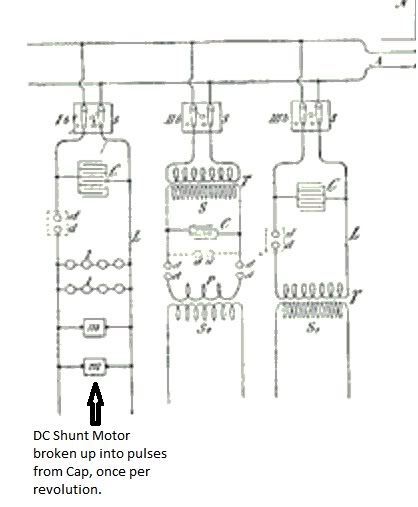
    The machine requires one DC motor, 555 timer circuit for pulses to chop the DC motor, one mono pole energizer and one large mass weight wheel. the two signals are out of phase from each other. and a capacitor tuned to the energizer. That is the mystery. other then that some simple wiring, you wont do it on a small scale.
    Hi John,

    Thanks for the explanation. Would like to know if the collapsing field's energy at any switch-off in the DC motor has also been used in the operation?

    One more thing: Aaron mentioned Radus boots and linked to the Bearden page for it. I wonder what is the relationship between the Watson (i.e. yours) machine and the Radus boots?

    I understand the flux switching in the Radus setup but Bearden mentioned the magnets Radus used had a memory.
    Does this mean that the Radus boots could not be built with normal off the shelf magnets? Or Bearden meant the memory effect for the Floyd Sweet setup?

    Could you give some explanation on these things I am puzzled by?

    Thanks,
    Gyula

    PS: in the meantime I realised the answer is yes for my question on the collapsing field in the DC motor, sorry.
    Last edited by gyula; 11-20-2010, 09:53 PM. Reason: addition

    Leave a comment:


  • redrichie
    replied
    Well no one said it did tie to the hub. But using the principles in the Radus boots I think I could see how to use it. Lets say we only had 2 coils on the hub. One "off" and one "on". Meaning in the "on" stage it would put the coil in attraction mode from the memory it would pull the magnet toward it. If properly space at the right timing a magnet should pass the "off" (no attraction) coil and generate a pulse that could be directed to the first "on" coil and shift its flux so the magnet would no longer be attracted to it and allow it pass. Flip flop these coils to off and on and the process could possibly keep the rotation going. Add more coils to aid in the process...
    Obviously oversimplified, and prob has nothing to do with that giant machine.
    Also I went down to Coral Castle and visited Ed Leedskalnins flywheel/generator. I saw what I though could have been many "perpetual motion holders" in the little tool area that was marked off. Lots of iron to manipulate flux paths.

    Leave a comment:


  • thedude
    replied
    Fantastic info!

    Originally posted by John_Bedini View Post
    Electricity,
    The mystery is none as it is right in front of you. I will give it to you again.

    The machine requires one DC motor, 555 timer circuit for pulses to chop the DC motor, one mono pole energizer and one large mass weight wheel. the two signals are out of phase from each other. and a capacitor tuned to the energizer. That is the mystery. other then that some simple wiring, you wont do it on a small scale. As I said it is right in front of your eyes. It's the way you think about it.
    Thanks John, for everything I mean. Regardless of my ( or other's ) technical incompetance, I personally have always found you to be a kind and generous individual with what you understand. Its not easy information to grasp initially. It takes trials on one's own behalf to discover the principles. Learning to fabricate and circuit building is something that i have had to struggle with. I'm getting a bit better at it, but i don't think i would have ever even tried if i hadn't found your work online. Its a joy to experiment, even through the failures there is so much to learn.

    Just wanted to say thank you.
    Last edited by thedude; 11-20-2010, 07:26 PM.

    Leave a comment:

Working...
X