
off time
Hello UFO i dont understand why the neon has any OFF TIME. Is it because we are pulsing the coil intermittently or is the neon intermittent or is SHE undecided? Thanks Al Sollid
-
Hi all,
Some time ago I was testing with this coil.
It is made with cat5 cable (network-4 twisted pairs).
I used 82 meters.
170mm outside, 52mm inside and 66mm in height.


Leave a comment:
-
@Cornboy: Your link seesm to be corrupt.
@qvision: Yes rotating magentic vortex. Download the booklet: "The secret world of magnets" from Howard Johnson"
@Lester:
My understeanding differs: As long we talk of linear range of core:
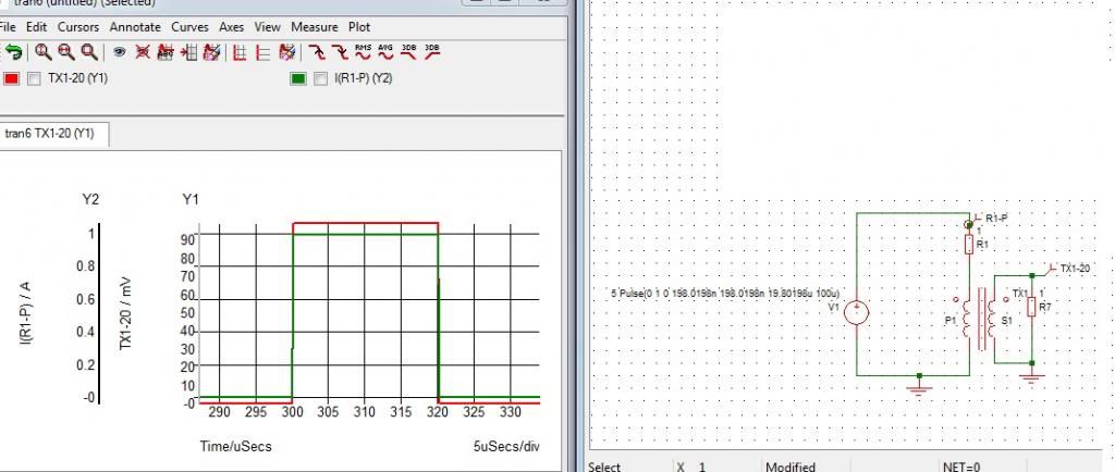
Constant voltage to a coil -> linear increase of primary current (probe it) -> conversion to secondary as image of the slope dI/dT of current and not the absolute current. If it were an image of absolute current we should have an increasing slope. The core will not transfer anything if current settels to a excessive high and stable DC current.
Yes a shunt can be measured. At higher temperature it increases its resistance. That's fine because at higher temperature FETs degrade their max. current.
The Allegro component makes use of a copper "shunt" as well but it is being checked in terms of hall effect. Advantage: galvanically separated.
Anyway: current measurement is a matter of further enahncements.Leave a comment:
-
Hmmmm.
Hello John, Lester ,All, could this be a good unit to drive motor coils?
Thanks Cornboy.Leave a comment:
-
Sorry Johnstone but I have to disagree with you. If you open up a SMPS you will find that some brands/models use this EXACT SAME method that I described with the toroid. What is your switching frequency anyway? A transformer will put out square-shaped pulses also (not just the edges as you said), if that's how your current waveform looks like. So not only the edges but also the top, IF YOUR FREQUENCY IS HIGH ENOUGH. Look at the CURRENT waveform on the graph below. The CURRENT is converted to VOLTAGE using the resistor at the secondary. I thought you knew how its done.Originally posted by JohnStone View Post
Anyway, if your switching frequency is low then I agree, the toroid concept won't work. You can take out the toroid and substitute a shunt in its place and you now have your overload protection. Same circuit as shown. You can make a shunt using a brass rod used for brazing. I have used 3mm brass rod as a shunt in a 40A application, with separate force & sense connections. Caution: the resistance will change with temperature and so the voltage drop will also change.
Regards,
Lester
Leave a comment:
-
Thank you UFO and John
Thanks UFO, it's great to hear your voyage of discovery
JS, what you are doing looks great, it's just way over my head at the moment, but i'm still learning
A member of another forum pointed out something from a book called From The Archives of Lester J. Hendershot, here is a screenshot :

Interesting, eh ?
I also like the fact that it seems the magnetic field of a permanent magnet seems to be in constant natural rotation.
Normal speed :
JK Plasma Magnetics Experiment 2 - YouTube
Slow motion :
JK Plasma Magnetics High-Speed Video - YouTube
Food for thought ...
All the best,Leave a comment:
-
I promized to build a sample for demonstrating driver PCB - SHORT wired - my style. But please note: it is a sample for crafting. The devices are different from true circuit but same shape out of my scrap box. Some wires and descrete components missing.

The driver bord top side view. You see there the drain as pin still unconnected but prepared for a bus bar. The devices soldered there symbolize the FET driver 9A, opto and 74c14 as signal shaper.
The driver bord top side viewHint: Any cap has a certain resonant frequency where it does not perform as cap. It depends mainly on shape and material. Therefore it is advisable to add different capacitors and shapes in order to get a blocking feature over the entire frequency range. The caps need to deliver up to 9A for short time of several ns. Forget it if you have leaded ones with long pins.
Please note: driving FETs is high current, high frequency. The only drawback missing is heat! Voltage drop, inductance ..... all apply here. Therefore SHORT MASSIVE connections.

Heat sink from an old Pentium PC recycled with driver being mounted. I added a threaded hole for mounting.

Another hint is to use bus bars out of copper for connecting source and drain if using multiple FETS for one channel. They are readily available at installers. They use them in order to connect the input of fuses at electric home installation. You see here some single bars and one as triple stack for three phase installaton. I hope this is not a local European phenomenon but you can get them all over the world.
This is the stuff momnster driver are built of. You decide on hat big or little monster you intedn to build. I hope I could add some understanding and help for further quality replications.
BTW. The pics were taken with an old Olympus 100RS. Original 1.4 Mpixel and shrunk to VGA format. They are still very clear. This indicates that good lenses are essential and not the Mpixel hype thy tell us to be essential.
JohnSLast edited by JohnStone; 01-14-2013, 09:07 PM.Leave a comment:
-
Thanks Ufo for teaching!
Some facts clreared up on others I continue to ponder!
JohnSLeave a comment:
-
Thanks UFOOriginally posted by Ufopolitics View Post
Yes, i will wait until the proper diodes etc arrive and do more testing.
I wasthinking of buying 3 x 12v SLA's but if i spend twice the money i can get a 30V/5A DC PSU, something i want to get anyway, so i will purchase one of those in time.
I am enjoying this very much and it is certainly intriguing, thanks for your time and patience with us all
All the best,Leave a comment:
-
Blew the neon, and it's my last one
No results at all with a 23W CFL.
All the best,Leave a comment:
-
Hello QVision
Hello QVision,Originally posted by qvision View Post
That's fine, excellent testing!, however I do not see on video a very well defined Time Off (Neon Completely Off)...at any point on video.
Basically the Orange Light is your Hot flow...and it is clear that it is steadily On...Now you kept forcing it at Higher Pulses and that triggered the Radiant in...but both currents were fully on, so it was a mix of Purple-Orange Light...and of course your Neon will get very hot.
Watch My Neon here:
RADIANT ENERGIZED NEON - YouTube
And you could pause it and note it gets completely turned off at times of primary start switching pulses...that is the idea.
Now, Your Diodes may not be filtering right and enough the Hot...but mainly, I do not see well defined Off Times there...It must Flicker, On-Off.
But You DO are getting there my friend!...so, keep at it and you will see HER much cleaner, brighter and with almost no Hot on...
Regards
UfopoliticsLast edited by Ufopolitics; 01-14-2013, 04:17 PM.Leave a comment:
-
@Lester, Cornboy
Regarding gate voltage:
i.e. IRFP460
Data sheet: 0.27Ohm at VGS 10V and 10A
The FET is rated for 20A permanent or 80A pulsed DC current.
----------------------
The 10V VGS will be suffitient for 60A (0.75Ohm). Above RDSon will increase considerabyl (2.0 Ohm at 80A) up to thermal FET death.
Increasing VGS above 10V will help in the range 60A ..80A to keep the RDSon below 0.75Ohm
-------------------------
Conclusion:
Higher VGS then specified in datasheet:
@ALL: I do not feel comfortable to pollute this thread being dedicated to pulsed coils. I am afrait most of you do not really know on stuff I talk above exactly in this post. We might need to find a solution for this.
@qvision!
Amazing you got this result within short time! These effects are a building stone to be added to UFOs asymmetric motors. In the past one of the members (can't remember who) drove a motor out of this energy and proved to not increase input power.
Nobody can measure the power out of radiant because our meters regard losses in order to interpret them as measurement. And radiant behaves very different. We have no meters for it just now.
Radiant is an effect of switched electrical power. Current science does not regard for it at all except protecting all sorts of electrical equipment from surge and other apparently malicious effects.
The high art is getting this energy interacting with matter in order to use it. You performed UFOs experiment successfully getting HER to interact with matter (neon). This experiment was an introductional tutorial in order make us grasp what stuff his motors make use of.
Thanks for taking the effort in order to read the whole thread! Hat up!
JohnSLast edited by JohnStone; 01-14-2013, 04:10 PM.Leave a comment:
-
This is basically an AC transducer. It will transfer at edges only.Originally posted by Lester444 View Post
DC transducers work with hall sensors inserted in to the ring ferrite. Manufacturers LEM
In fact we do not need true measuring but an overload protection only.
I remember to have built a burgler alarm for my car. I measured the voltage drop via + line when the internal light switched on - and it worked well. So we do not need a shunt but a short piece of copper wire. The main concern will be to prevent noise from HER.
Alternatives possible (current technology):
Allegro produces hall current sensors for DC up to +- 30A and galvanically separated.
Purchase breakout board here It is a Pololu open source breakout board. $9 is quite intriguing!
Extension for amp range by adding a piece of coppr wire as shunt The internal "wire" is copper as well. (less accuracy!)
I need to ponder on it but take this as thought food for now.
JohnSLast edited by JohnStone; 01-14-2013, 04:12 PM.Leave a comment:
-
Did a quick video, plasma occurs after 1:27 :
Simple version of UFOPolitics' cold-electricity coil. - YouTube
All the best,Leave a comment:
Leave a comment: