Announcement

Collapse
No announcement yet.

My Motors got me to Tap into Radiant Energy

Collapse
X
 
  • Filter
  • Time
  • Show
Clear All
new posts

  • JohnStone
    replied
    Originally posted by Cornboy 555 View Post
    www.micrel.com/_PDF/mic4451.pdf

    Hello John, sorry to here of your troubles, hope all is well soon.

    When you get a chance could you please view this driver and let me know if it would be a good one for driving the coolmos set up and, or, the SiC fets.

    Would you still require the conditioners (74c14's)?

    Would it have same pin out arangement as UCC27421?

    Would you use 1 per coolmos or cree fet to be best possible?

    Sorry for questions in troubled times, Friend, please answer at your leisure.

    Thanks Cornboy.
    Hello John, sorry to here of your troubles, hope all is well soon.
    Thanks to @ALL for your compassion I surely will overcome but it takes lot of workload and patience. So I will restrict myself to electronics. For building the motors we have excellent experts herein.

    When you get a chance could you please view this driver and let me know if it would be a good one for driving the coolmos set up and, or, the SiC fets.
    That is a monster as well. If it is availale on international scale I will switch to it! We need to deside for inverting or non inverting type.
    Fortunately this component can be puchased along coolMOS at Farnell.


    Would you still require the conditioners (74c14's)?
    They have some means of conditioning. I ponder just now on over current protection and it will be acting in the area of signal conditioning but modified. Please let's have a final talk along a circuit diagram provided by me and reviewed by Lester or others before you place orders. I will align my own build to it.


    Would it have same pin out arangement as UCC27421?
    Obviously yes.

    Would you use 1 per coolmos or cree fet to be best possible?
    It depends.
    1. The driver can drive up to 62 nF that corresponds to about 6 FETs. (Additionally to the gate capacitance of about 1nF in real switching operation we suffer on different side effects. These can be estimated to be 10nF)
    2. We have to account on how the charges can be delivered / retracted to/from the FETs. SHORT / FAT wires / NO sharp bends. Vote this to act like grease or oil to a hevy duty machine. This is necessary in order to get the FETs switching in the very same time slot. (else we suffer an ringing, poor performance and heat)
    If we imagine 2 FETs being arranged back to back on heat sink we can imagine to have another identical pair near by. This arrangement can be build short and symmetrical. If using the coolMOS suggested we can pulse more than 400A for short time and load them with 150A average continuously. More performance if excessive cooling.
    3. I suggest to evalute with 2 FETs first and watch the switching degradation (if any) when adding another pair.


    Sorry for questions in troubled times, Friend, please answer at your leisure.
    You are welcome. Nobody is perfect (I refere to me) and I take all questions and hints as chance to elicite the suggestion. Together we are strong.
    Last edited by JohnStone; 01-22-2013, 10:42 AM.

    Leave a comment:


  • Cornboy 555
    replied
    Solonoids.

    Automotive and Heavy Duty 12 & 24 Volt DC Electrical Components

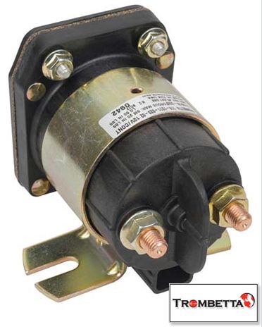
    Hello UFO and all, these guys stock soloniods that can switch 800 amps continiously, and a control module that can switch them from TTL signal.

    But of course they are mechanical products that wear out plungers etc.

    I don't know what you had in mind UFO, but you would get a hell of a kick from those solonoids at turn off.


    Regards Cornboy.

    Leave a comment:


  • Cornboy 555
    replied
    Looks Maybe Good.

    Originally posted by Ufopolitics View Post
    Hello to All,

    Hello My Dear Friend John Stone, and hope all will be just fine and everything gets a happy solution.

    I have been testing/working also on this Controlling of the Imperial Motor, however, I am not involved in the Electronic side as of now.

    I believe I will be bringing a Solution for all...meaning, electronics will not have to be "Monsters Switchers"...managing very high amperage's and voltages...but working very relaxed...and cool.

    I am still working on it...and making a video off it.

    It is based on a Solenoid, used on Golf Carts...for those who do not know...they make this things for 100- 200Amps...and more.

    [IMG][/IMG]

    A Solenoid is just a Relay, with a low voltage Coil, and the heavier duty contacts to run the Electric Motor and Controllers, normally the Coils are rated for 12V, and have a resistance from 60 to 120 ohms...They are normally open switches...as also they work to be either steadily On (during run time) or Off...

    Tell You what am making?...Nah...better once that I test it...

    Once that I verify it works ok...I will post everything...so you Guys do not keep frying your brains, finding such heavy duty FET's...


    Regards


    Ufopolitics


    Great UFO, i have had a brief excursion down that track, i will try to at least post links to what i found.

    Warm Regards Cornboy.

    Leave a comment:


  • Ufopolitics
    replied
    Hello to All,

    Hello to All,

    Hello My Dear Friend John Stone, and hope all will be just fine and everything gets a happy solution.

    I have been testing/working also on this Controlling of the Imperial Motor, however, I am not involved in the Electronic side as of now.

    I believe I will be bringing a Solution for all...meaning, electronics will not have to be "Monsters Switchers"...managing very high amperage's and voltages...but working very relaxed...and cool.

    I am still working on it...and making a video off it.

    It is based on a Solenoid, used on Golf Carts...for those who do not know...they make this things for 100- 200Amps...and more.

    [IMG][/IMG]

    A Solenoid is just a Relay, with a low voltage Coil, and the heavier duty contacts to run the Electric Motor and Controllers, normally the Coils are rated for 12V, and have a resistance from 60 to 120 ohms...They are normally open switches...as also they work to be either steadily On (during run time) or Off...

    Tell You what am making?...Nah...better once that I test it...

    Once that I verify it works ok...I will post everything...so you Guys do not keep frying your brains, finding such heavy duty FET's...


    Regards


    Ufopolitics

    Leave a comment:


  • Cornboy 555
    replied
    Driver's.

    www.micrel.com/_PDF/mic4451.pdf

    Hello John, sorry to here of your troubles, hope all is well soon.

    When you get a chance could you please view this driver and let me know if it would be a good one for driving the coolmos set up and, or, the SiC fets.

    Would you still require the conditioners (74c14's)?

    Would it have same pin out arangement as UCC27421?

    Would you use 1 per coolmos or cree fet to be best possible?

    Sorry for questions in troubled times, Friend, please answer at your leisure.

    Thanks Cornboy.
    Last edited by Cornboy 555; 01-22-2013, 04:16 AM.

    Leave a comment:


  • prochiro
    replied
    @ JohnStone
    Thanks so much for clearing that up about the version issue.
    I wand a good setup that does not push the ic's to there max. Parts are trickling in now and should have them all in a week. I should be done with the Quad setup by then and ready to go. Take care of what you must at home and know that we will be fine.
    Dana

    Leave a comment:


  • JohnStone
    replied

    Leave a comment:


  • JohnStone
    replied
    Pulser 555 V3

    OK friends. May I introduce: Pulser 555 V3
    I divided in two parts: DRIVER and FET Stage. It is still preliminary as I want some of you to check it.
    DRIVER:

    For power feed it is recommended to use a separate PSU like a socket charger. At left hand side you have the choice if feeding 12v directly or you step it down to 12V.
    Choose at 555 pin 1 or near to positioning a central GND point from where you wire the components in star shape or massive wire.

    FET Stage:

    - Choose your FETs to have the sum of max. current to be half the current you intend to draw. This is important because the they derate by heat and other influences temporarly.
    - Choose the max. voltage to be 1/3 of your supply at power side to allow clearance for voltge spikes. Nevertheless be careful and use the test circuits shown at right hand side.
    - It is essential to wire this stage with SHORT wires.
    - Cut the gate pins to some mm.
    - Solder non inductive resistors (metal film or SMD) directly to gate. Make both lead SHORT. Join the resistors at other side and connect the wire from driver.
    - Proceed with diodes 1N4148 in similar way. Solder the GND of zener diode /cap SHORT to drain bus bar.
    - Do not drive more than 2 FETs from one driver. The switching property will derate considerably (less radiant). Instead build another identical stage along driver and test it separately. Join them later on. Scale it further if you decide to.
    -Use test circuits first in order to prevent smoke! Discharge peak detector prior to measure. Wait voltage on meter to settle. Then you have an indication of peak voltage.

    BOM:
    Last edited by JohnStone; 01-21-2013, 10:16 PM.

    Leave a comment:


  • JohnStone
    replied
    Voltage suppressors:
    Currently at eBay BZW0613
    It is bidirectional but that does not matter.

    There are plenty of types being usable. They call them TVS, transzorb, transil, BZW, 1.5KE ...
    Makes from: ON-Semi, STM, Vishay, Protec, ....
    Thus it is very difficult to give any advice for worldwide purchase.

    Hints:
    Voltage supperssors are defined for an operating voltage = VRM and a a voltage at beginning of clamp function (Ir= 1mA) VBR. Additionally they are defined for serious currents (Ipp) and the correspunding clamp voltage (VCL).
    But VCL does not matter here because we will not exceed 1..3 A for short time.
    Given you feed the 555 by 12V you loose some voltage through 555 and one transitor BE-junction = app. 1V. So the gate will get 11 V max. at normal opration.

    -Type BZW06-13 was made for an operating voltage (VRM in data sheet) of 12.8V. It will start to conduct at 14.3V (VBR @ 1mA) being well above 11V and well below 20V accepted by FET as maximum. This voltage will remain quite stable up to 1..3 A.
    - Same for type 1.5KE15 -> VRM=12.8V / VBR=16.5 max
    - 1N6267A series (ON-Semi) = 1.5KE15 = P6KE15A

    Do not worry if yu do not understand those facts. We will find a solution for you.
    This facts in advance. Let's discuss it related to the new circuit diagram I will post soon.
    JohnS

    Leave a comment:


  • JohnStone
    replied
    Originally posted by prochiro View Post
    JohnStone
    I am building circuit for Imperial motor and wish to understand about direction to go. I see one circuit with 555 and on post 1610 another with IRFB4137PBF. Are there two platforms going at same time or or was post 1610 food for thought. It seems as post 1610 is stronger of the two. Help with clarification.
    Dana
    Hi Dana,
    Oh yes it is confusing, sorry. There are two platforms indeed. One with 555 for low fund and performing quite well. The second is more expensive and will be the ultimate one (and expandable) for all sorts of power experiments. It is like in real life: we need both tractors and racing cars. It depends on requirements. Eventually we get a racing tractor if required
    I will clarify it soon. Just now it is early AM night time. I watched the thread because lag of sleep. Stay tuned you will get help.

    Hi Lester,
    thanks for advice. I will search for some alterntives for BZW05 - there are plenty of them availble.

    JohnS

    Leave a comment:


  • prochiro
    replied
    Hello John @ Lester
    I just checked here in the states at Mouser/Digikey/Ebay and the BZW06-12 does NOT seem to be there with minimum orders of 7000. Also is that bidirectional or not.
    Dana

    Leave a comment:


  • Lester444
    replied
    Originally posted by JohnStone View Post
    Hi Lester,
    thanks for suggestions. I have absolutely no problem to be corrected! And you are terribly right: we have the very SAME goal!
    Well:
    Using 1n4007 was superficial, just copied from elsewhere. You are absolutley right with your suggestion for 1N4148. I will correct it today.

    Zener diode: Yes you are right with this suggestion but I do not trust in pure zeners in respect of accuracy and speed. We had bad experience with those. If the data sheet does not tell about a proprty for a component -> vote it to be bad and may vary from lot to lot, though the simulation shows nice results.
    But I still agree given we suggest suppressor diodes. Those are made to swich very fast and are rated with better accuracy. Do you accept BZW06- 12 or BZW 06-15? datasheet

    May I direct you to the capacitance of about 1.5nF? That is terribly for high switching speed.
    I would suggest to replace 1N4007 by 1N4148 and feed the cathode to a BZW06..... Thus we get rid of the capacitance and make use of zener effect.

    Please utter your opinion!
    JohnS
    Hello John,

    Yes BZW06-12 would work nicely. The only downside to that is it is not easily available worldwide so some members might have difficulty in getting those. In such a case they will have to use regular of-the-shelf zeners.

    I think your idea would work well: BZW06-12 in series with 1N4148 and placed across the Gate pin and Source pin of the FET.

    Lester

    Leave a comment:


  • prochiro
    replied
    JohnStone
    I am building circuit for Imperial motor and wish to understand about direction to go. I see one circuit with 555 and on post 1610 another with IRFB4137PBF. Are there two platforms going at same time or or was post 1610 food for thought. It seems as post 1610 is stronger of the two. Help with clarification.
    Dana

    Leave a comment:


  • JohnStone
    replied
    Hi Lester,
    thanks for suggestions. I have absolutely no problem to be corrected! And you are terribly right: we have the very SAME goal!
    Well:
    Using 1n4007 was superficial, just copied from elsewhere. You are absolutley right with your suggestion for 1N4148. I will correct it today.

    Zener diode: Yes you are right with this suggestion but I do not trust in pure zeners in respect of accuracy and speed. We had bad experience with those. If the data sheet does not tell about a proprty for a component -> vote it to be bad and may vary from lot to lot, though the simulation shows nice results.
    But I still agree given we suggest suppressor diodes. Those are made to swich very fast and are rated with better accuracy. Do you accept BZW06- 12 or BZW 06-15? datasheet

    May I direct you to the capacitance of about 1.5nF? That is terribly for high switching speed.
    I would suggest to replace 1N4007 by 1N4148 and feed the cathode to a BZW06..... Thus we get rid of the capacitance and make use of zener effect.

    Please utter your opinion!
    JohnS

    Leave a comment:


  • Lester444
    replied
    Hello John,

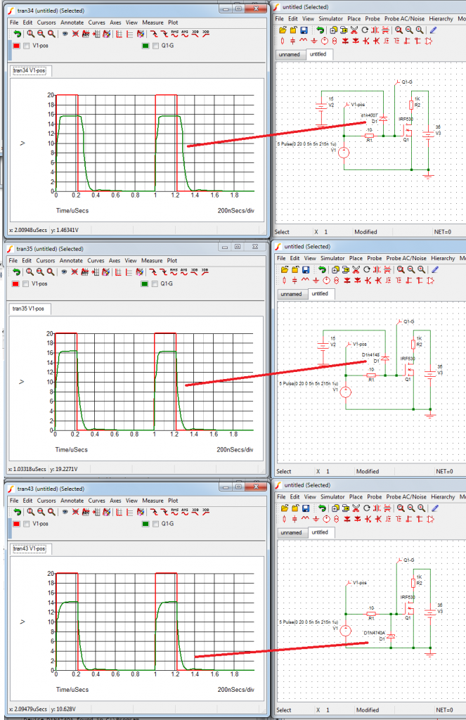
    In your circuit, I am concerned about 2x diodes at gates of FETS, 1N4007. This diode has poor switching properties and is NOT normally used for fast switching. You get better switching characteristics with 1N4148 diode.
    See graphs below. I do know you are concerned about momentary high current at the gate also, several amperes to charge the gate capacitance and 1N4148 might not handle the current.

    I normally use a zener diode at the gate for protection since it is fast and also protects against negative voltage at the gate. This is the third graph in the picture below. Additional benefit is that there is also one less wire going to the FETs.

    We all have basically the same goal here and I just thought I might warn you about those 2x diodes.

    Lester

    Leave a comment:

Working...
X