
Just used the 1610 post dgm
@Dana
to try to get how to hook up the Arduino PWM pins to the MD_5.1 board. Don't see what that R2 is doing on input connector...
Edit post 1974: I meant to say Opto A,K not A,B...
Yes interested in those CAD files, sent you a PM.
-
@ Sampojo
I see you may be looking at different versions and getting confused.
Those diagrams were confusing for me and are not complete as per version 5.1-prerelease PDF is. I would set up the parts as per the latter file shows and hook her up. If you want a cad file for T3000 I can send it to you. T3000 is free and easy. the file there is ready for sending out to production.
Easy, easy, easy.
DanaLeave a comment:
-
I found an answer I think
Q2: Schmitt Triggers A & B are extra/ not used? 74HC132N is a Quad DIP with a total of 4 triggers.
When I get my schematic and CAD board layout together using ExpressPCB, I will post the files. Then anyone can order the PCBs using their software. Probably get 3 MD5 prototype boards estimating in $50-100 USD range. Layout is coming along...Last edited by sampojo; 05-22-2013, 04:23 AM.Leave a comment:
-
Update
Hi UFO,
I am going to run the test this week, been very busy and I started a new job today and I have a lot of reading up to do.
Also I was able to remove the bearing and commutators off the shaft. I need time during the day to bring at a shop where the guy is willing to freeing put it in the oven for me
JoelLeave a comment:
-
Getting Down on the MD5 circuit
Some Questions on the MD5. I have labeled it with the areas I have questions:
MonsterDrvrV5_labeledpost_zps801874a5.jpg Photo by sampojo | Photobucket

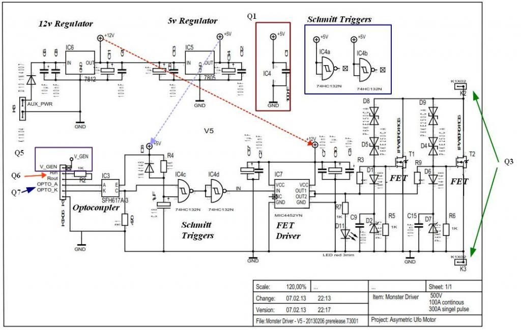
- Q1: Does each Schmitt Trigger get encased in this circuit?
- Q2: Where do Schmitt Triggers IC4a and IC4b fit?
- Q3: Is this +, power out and GND (-)? IN the BOM, lines 34,35: 34 K2 K1X02 1X02 connector pitch 2.54 / 2 posts 35 K3 K1X02 1X02 connector pitch 2.54 / 2 posts?
- Q4: Is K3 just 1 (0f 2 posts in a 2-prong connector, and K3 is the other, or is this still a total of 4 poles, 2 + and 2 GND? If the latter, is this just an extra connection to be used as circumstances may require?
- Q5: What is VGEN, where does it go?
- Q6: Are these used with the Arduino connection?
- Q7: Are Opto A, B the PWM hookups, as maybe with the Nano outputs D3,4(pins 6,7)?
For Q6, I see resistors in this diagram from JStone P54 Post1610. I assume Opto A,B are similar?

Planning to use tools from ExpressPCB, shematic and CAD programs provided for customer prototyping, saw prices 5 PCBs/$35.Last edited by sampojo; 05-21-2013, 02:05 AM.Leave a comment:
-
Joel,Originally posted by lerameur View Post
Do You mean 500Hz at Hot or Cold side?
Do You have Two Frequency Meters on, like I recommended?...One at Hot side and another at Cold, is the way to monitor IF You are getting higher frequency after diodes (Radiant side) like you are supposed to get.
3) I get the feeling I am not getting radiant in because, if I stay at lower frequency and play around with the duty cycle, The longer the dutycycle the stronger the light.
Try hooking up a 120V Neon at Radiant side...then start dialing Up slowly the duty cycle from zero...very slowly and watch if you see a purple very bright ball of light, bouncing around electrodes...at very low pulses only...DO NOT GO HIGH...IF color of light is only Orange.
I do not think it is the cores/tubes...I wrote it -also- beforeI am going to find some two inch plexiglass tubes, but that was all I could find nearby my house. I have some strong cardboard roll, but they are 3 1/4 inch OD. too big. I'll see what i can find at the dollar store tomorrow.
Joel
Let me know after you do this tests
Regards
UfopoliticsLast edited by Ufopolitics; 05-18-2013, 03:51 AM.Leave a comment:
-
HI UFO,
O sorry I missed that,
They are all connected in parallel
JoelLeave a comment:
-
Originally posted by lerameur View Post
Joel,
The greenish light at CFL's...You will not see it with your own eyes...but only on videos, slowing then down, or framing pic by pic...as it only happens at a fraction of time, not distinguishable by Human sight...and it is JUST at the beginning when radiant starts coming in...
I asked You on my previous post, How are Your Bi-Filar and Tri-Filar Coils terminals connected?
Parallel or Series?
UfopoliticsLast edited by Ufopolitics; 05-18-2013, 02:07 AM.Leave a comment:
-
Maybe My english is not great. But all work at certain degree. But I cannot get to see is:
1) the greenish light from the CFL, I am seeing on some of the videos on the forum (youtube)
2) I get no output beyond 500Hz, I mean the light is extinguish
3) I get the feeling I am not getting radiant in because, if I stay at lower frequency and play around with the duty cycle, The longer the dutycycle the stronger the light.
I am going to find some two inch plexiglass tubes, but that was all I could find nearby my house. I have some strong cardboard roll, but they are 3 1/4 inch OD. too big. I'll see what i can find at the dollar store tomorrow.
JoelLeave a comment:
-
Originally posted by lerameur View Post
Hello Lerameur,
Great, and that it's ok...I figure them (connections) out...
Sometimes they use Carbon fibers to strengthen material...and if they are crossed, they will kill Radiant Field...However, IF, the First Coil works fine and have same material as core...then, that is not the issue here...
I see/read you are using Bifilar and Trifilar wound Coils at the "Not Working Ones"...are they -hopefully- parallel connected?..not meaning how are they wound...but connected at end terminals.?
UfopoliticsLast edited by Ufopolitics; 05-18-2013, 01:26 AM.Leave a comment:
-
The connections is exactly the way you showed, sorry about not putting that on. Thought you wanted a schematic!
I am so not sure if there is or not carbon fiber...
I guess i should find another 2 inch tube to test it on/with ?
JoelLeave a comment:
-
Missing Diagram...
Hello Lerameur,Originally posted by lerameur View Post
They look nice...but you forgot to give me the diagram of your connections...
Here, I made the way it supposedly goes...
[IMG]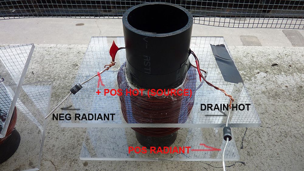 [/IMG]
The Polarity is set according to how you have your diodes connected there...All Coils must display their South Pole on Top.
One question...that is "Black PVC" as the core...and you are sure it does NOT Contain Carbon Fibers??
Regards
UfopoliticsLeave a comment:
-
my three coils
Thanks for your time UFO,
here is a picture of all three coils.
They wound clockwise
the resistances are:
Big coil: 0.65Ohm
Medium coil: 0.85Ohm
small coil: 0.6 Ohm
19Awg gauge.
This is more then 200 turns. The two bigger coils has 200 feet and the smaller has 150 feet. these length are for individual coils.
The Resistance for the big coil was taken with the the individual coils hooked together as seen on the picture.
JoelAttached FilesLast edited by lerameur; 06-02-2013, 11:54 PM.Leave a comment:
-
-
Magnificence of 3
This is a phrase coined by our illustrious leaderOriginally posted by asollid View Post
 Ufo. It refers to the most powerful design he has posted so far. You may find it first presented HERE. It is the design cornboy jumped on with 2 feet as you may notice.
There is a tremendous amount of material, real science, in these threads. Read them all, and save every page.
I have a reference document I have made to help me understand things. I will be changing it as I assimilate more material myself.Leave a comment:
-
Hello Lerameur
Hello Lerameur,Originally posted by lerameur View Post
There MUST BE something wrong in your Coils windings when you add Second and Third to the First Coil (that worked)
It is very important to have in mind that ALL Coils (when you are winding One on Top of the Other) They all MUST BE WOUND with EXACTLY same directions of windings.
If You do one CW...and the Second CCW...you will be canceling the Hot Magnetic fields between them...or weakening to almost a zero resultant....Therefore Radiant Field will not be generated at the Off Times.
Could you post a Diagram of how are you connecting them with diodes and between them and Oscillator?
It will help me a lot to see that.
Thanks
UfopoliticsLeave a comment:

Leave a comment: