
resistors
@JohnStone
John, which resistor should I play with to get better pulse after the opto. I am getting improper mix and always on state into IC4. Is it the 470 Ohm resistor? What ever one it is may need to be greater resistance. System supply is 18V and getting a clean 12 volts thru 7812.
Dana
-
@bro d and all
When making a PCB board with the etching method follow this procedure.
1. Print out the drawing at the bottom of the V5.1 manual.
2. Lay the copper clad board out on the table so that the copper side is up.
3. Turn the printed picture over so that the print side is down and lay it on the copper top.
4. This is the correct orientation for etching. There are many internet references on how to etch. Clean it up with a lacquer thinned rag to get any unwanted lines and such off the board before heating and again after etching to get it clean and bright.
5. What you will see on your board is the correct back of JohnStones drawing.
6. I really hesitate to get into a conversation of mirrored or not mirrored as it gets crazy relative to if you are doing a one or two sided wired board. It just happens that JS has printed the top drawing here and for a one sided bottom, it is the same LOOK as the bottom mirror print.
DanaLeave a comment:
-
Warresk posted in teh otehr thread:
Hi Warrensk,Originally posted by warrensk View Post
as I mentioned before you are inventive! Unfortunately your driver circuit is less effitient, dangerous for your FETs.
Different from transistor a FET is being controlled by voltage and not by current. Imagine a FET to have a parasitic capacitor between gate and drain (1nF). You charge it but have no means for discharge. So the shut down is undefined.
If you decide to use a NE555 circuit as simple FET driver you will get a major enhancement.
More advise on request.
JohnSLeave a comment:
-
mirroredOriginally posted by prochiro View Post
MIRRORED Photo by brodonh | Photobucket
unmirrored
MIRRORED Photo by brodonh | Photobucket
Attempting to save some time and grief.
bro dLeave a comment:
-
Just a quick thank you to JohnStone.
That is a very nice professional looking circuit and manual you have designed.
I personally wish to thank you for your generosity and hard work.
Thank you for sharing.Leave a comment:
-
Donald, Donald Donald
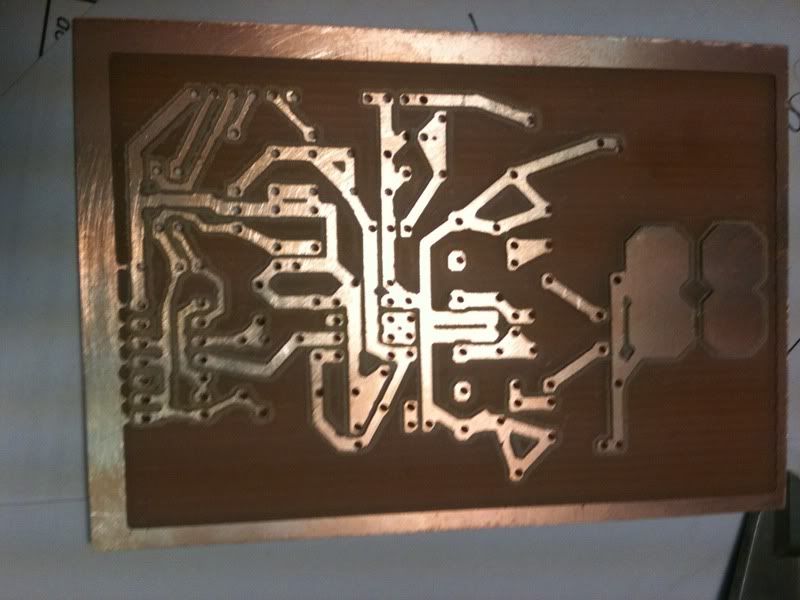
The PDF picture is the one you print on a laser printer and heat press on the back side. I did that and it works fine. I also got into T3001 and exported the G-code for the bottom (which had no writing on it and automatically mirrored), then ran the three files on the mill. one for holes, one for isolation of wires, and one for removal of all extra copper surface. You are looking at the bottom of my board so flip it over in your mind and see it like JohnStones pictures. It is confusing if you mix both types of production in your mind at the same time.
DanaLeave a comment:
-
Hi JohnS,Originally posted by JohnStone View Post
Thanks for the response.
I worded my question with redundance to the point of confusion.
If Dana's pic and the mirror image in V5.1 are identical then there seems to be an error.
The unaltered pic of the copper etched on the bottom of the pcb has to be the "anti-mirror".
Please check,
Regards,
DonaldLeave a comment:
-
RMCybernetics.
Originally posted by JohnStone View Post
Hello John, RM Cybernetics in England would build this driver for us, but i wouldn't feel confident enough to talk to them about it myself.
I am sure you or Dana could communicate what was necessary.
Regards Cornboy.Leave a comment:
-
Manual for Monster Driver 5.1
Thanks for your patience!

- Now I dare to release LAB NOTE 004 - the current manual for Monster Driver V5.1. It is still labelled with "prerelease". It will be finally released if several replications were proved to perform well.
- First publication in the forum was here
- Discussions and valuable knowledge can be found starting with this post
- Data published for milling here
I am so sorry that some of you are not experienced in electronics. Thus you might get lost. I tried my best in order to keep things simple and understandable by non professionals. Else consult the forum where I posted plenty of knowledge regarding FETs and other electronic knowledge.
I enjoyed developing this driver and sharing it with YOU. I will focus from now on preferred on Arduino control and own lab work.
BTW: I remeber there was a discussion regarding a company being eager to rebuild such circuits? Was it Sparkfun? They build PWM pulsers as well. If they are interested and build this driver we could get plenty of professionally made drivers? Some suggestions?
JohnSLast edited by JohnStone; 02-20-2013, 11:06 PM.Leave a comment:
-
Hi tomturbo80
As I recall that circuit worked as shown. There was two versions of that circuit. The one you should be working on has a wire from D3 running more or less straight down to ground on bottom of picture. Are you using 36 volts? That might make the difference. The 47K's are so high resistance that removing them should not make that much difference unless you had them tied in series rather than parallel. I believe they were to prevent overload as a pull-down to get fets off fast. Check your circuit for any other difference in parts and correct method of wireing. Helping you is our pleasure, just make sure that every posted question keeps us informed of the exact circuit you are working on as JohnStone asked. UFO has gotten a lot of miles on that circuit.
DanaLeave a comment:
-
Donald,
please note there are two different sets of data available:
Initial realease as PDF:
Same release but manufacturing data being generated automatically by CAD: http://www.energeticforum.com/renewa...tml#post224748
Some text was entered in PDF manually for explanation. Thus it is no wonder to have some differences being of no importance for the layout. But I admit you are very attentive!
Sorry for confusion!
Please do not use grafic dataout of my V4 PDF for layout. I will revide it soon to be conforming V5.1 version.
JohnSLeave a comment:
-
Mirror?
Hi Dana,Originally posted by prochiro View Post
I need to be sure of something regarding etching these ccts.
I was just about to post regarding your previously posted etching, because when I etched mine I could read the text in the copper.
I noticed that your pics do not appear to be the mirrored image etched on the pcb.
Your pics are the same as the image appears in the pdf, which is the mirrored image unless I am mistaken.
Perhaps you mirrored your pics ..........
When I am looking at my etched pcb, the text "Monster Driver v5.1" is in the upper left hand corner. Yours (if the text was visible) would have to be in the lower right, with the heavy copper connectors on the right in both cases.
I have to look through the component side for mine to line up with yours.
Shouldn't I be able to read the text after etching?
Regards,
DonaldLast edited by Donald Haas; 02-20-2013, 06:07 PM.Leave a comment:
Leave a comment: