Does it make sense that the 'potential for lenz' starts at the moment the magnetic field begins to influence the coil? This would mean that the timer starts before the magnet reaches the coil. This field size can be figured out by using a field calculator like this one... K&J Magnetics - Magnetic Field Calculator
Anyways, I haven't looked at your numbers closely enough to tell, but I just want to make sure I understand it right. when we are calculating the distance that the magnet must travel we need to include in that the "reach" of the magnetic field. Correct?
-
I'm wondering by how much we need to beat the rise-time, i guess there's an optimal point, would we want to be at TDC at half the rise-time ?Leave a comment:
-
@ AB, excellent idea, i already have a cheap tach and a 20 x 20mm diametric tube magnet plus carbon rod for the axle !
Thanks AB
Leave a comment:
-
Math.
@geotron,
Looks interesting. Can you upload a video? What's your rotor RPM at "Lenz Reversal"?
@qvision
Your math looks pretty solid, but 1473 RPM'S is really retarded. Try a no bearing 1/2 inch diametric tube spinner on a small ball bearing. Get a cheap laser tach from Harbor Freight or on e-bay for $35. The bearingless spinner should easily travel ten times as fast as your rotor, and the propulsion effect should be imediate and help center the rotor. Real cheap and easy soloution.Last edited by Allen Burgess; 09-11-2011, 04:05 PM.Leave a comment:
-
I've been thinking about calculating the minimum RPM needed for the effect to kick in and then testing it.
All of these values are for components i have lying around and the gen coil is probably highly unsuitable.
Coil Inductance L : 0.01756
Coil Resistance R1 : 19.2
Load Resistor R2 : 220
Time Constant = L/(R1+R2)
TC = 0.01756/239.2 = 0.0734113712 mS
So, to beat the rise time the magnet must pass over the core very quickly.
Rotor diameter is 150mm, magnet dia is 20mm and flush with outer edge of rotor so magnet centre point is 10mm in from from the outside so the effective diameter is 130mm and our effective circumference (the travel line through the magnet's centre) is Pi x D = 408mm.
Let's say the magnet has to pass over the core in 0.07ms, so it must travel 10mm in 0.07ms.
Mutiply by 1000 to get us to seconds and meters =
0.7 seconds to travel 10 metres (10,000 mm).
The circumference to travel is 408mm so 10,000 / 408 = 24.509
So it has to rotate 24.509 times per second.
RPM = 24.509 * 60 = 1470.54 RPM.
Damn ! I'm testing as i'm typing, if i rotate my rotor anticlock it only gets up to 1482, clockwise it's max is 1473.
Oh well !
Can someone double-check my maths ? I'll stick it in a spreadsheet and post a link.
QV.Leave a comment:
-
OK i think I worked this out now.
A parallel wound, series connected coil the current flows the same direction so it is inductive but the capacity is increased because of the increased potential between windings.
A non inductive coil has the current flowing in adjacent windings in opposite directions and so is cancelling.
This I learned from the wiki link qvision just posted. My appologies posted on the previous page.
This one.
Bifilar coil - Wikipedia, the free encyclopedia
It says the four kinds of bifilar windngs just below the picture there.
..Last edited by Farmhand; 09-11-2011, 02:40 PM.Leave a comment:
-
When we say we want to beat, using your example, the 0.48 mS rise-time, do we want the magnet to have completely crossed the core in less than this time, or just reach TDC in less than this time ?
I am doing a quick spreadsheet to calculate the minimum RPM needed given a certain coil/load etc ...
QV.Leave a comment:
-
This may be right, and you're test results are likely valid, my series connected solenoid coil measure's 4 x more inductance than a single winding alone or two in parallel. You may well be right about the increased capacity but in a solenoid the windings would end up on top of each other and at angles and such, seriously reducing the full possible effect or ballancing effect.Originally posted by Allen Burgess View Post
My contention was that a serial connected parallel wound flat spiral coil is kind of self inductance-self cancelling. In that because of the way it is wound there is a larger potential difference between the turns thereby a greater capacity. The coil becomes resonant in my opinion at certain frequencies. Because it is it's own tank. EDIT: not needing an external capacitor for resonance at a desired frequency or something.
I'm not sure this potential difference would be uniform in a solenoid like a pancake. But it will still work.
Also I have never doubted the effect is real.
But is it usefull ? Maybe
Is it really Thanes idea ? Dunno. No comment.
Can it be the vehicle for overunity ? Possibly.
Is thane aware of the Tesla coil for electromagnets ? I would guess yes.
NIKOLA TESLA - Google Patents
This patent also includes helice's, solenoids and any other coil.
So you are correct. Yes. In my opinon. As covered by Nikola's patent, this effect would in fact be present in a solenoid coil.
CheersLast edited by Farmhand; 09-11-2011, 02:11 PM.Leave a comment:
-
Bifilar coil capacitance.
@Farmhand,
Charge a spool wound series connected bifilar if you have one, just by holding the two wire leads to a pair of battery electrodes for an instant. Check the coil for a stored voltage charge with a multi-meter set to the Milli Volt range.
Try this experiment with a single wrap high inductance, and compare the capacitive charge results to the spool wraped bifilar. I can assure you the spool wound series wound bifilar acts as a capacitor, just like the Tesla spiral pancake.
This is a feature Thane Heins may not be aware of, but I can assure you'll find the capacitance there. I can also assure you that the bifilar will increase motor rotor acceleration, the output is double the voltage of a parallel wireing that has lower capacitance and rotor acceleration equal to a single wrap.
Combining a thin wire with the hi-voltage bifilar series wireing, maxamizes rotor acceleration as tested by me. Don't take my word for it. It's too easy to test for. Maybe someone else can help confirm this effect. This is very important, and completely understandable thanks to Thane's enlightened analysis. We should be able to graph this effect as Overunityguide did with RPM, coil charge and Ohmic measurements.Last edited by Allen Burgess; 09-11-2011, 12:08 PM.Leave a comment:
-
 Guest replied[ Recovering motor energy while charging 6v storage ]
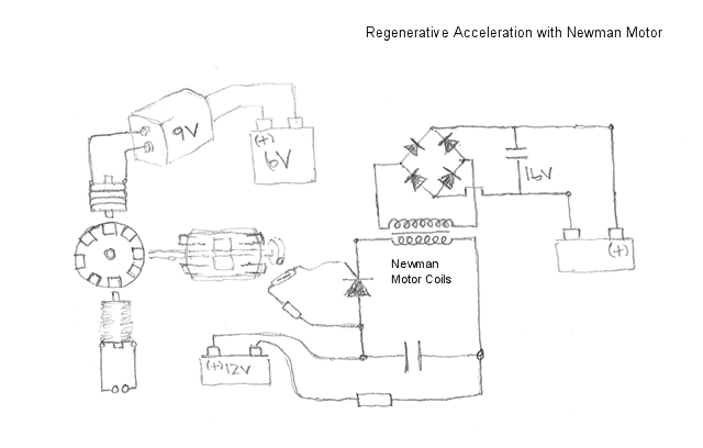
Leave a comment:
-
Hi You All,
Please See my Latest Video About: 'How to Calculate the Delayed Lenz Effect'
Calculation of the Delayed Lenz Effect - YouTube
This Video demonstrates how we can calculate the desired Delayed Lenz Effect, and shows that the experimental results of my previous video about: the Difference between Loading and Shorting the Regenerative Acceleration Generator coil can be explained and can be calculated. So than again high impedance is really important. And the Lenz Delay can be calculated by L/R
With Kind Regards, OverunityguideLeave a comment:
-
Guest repliedWhen the generator coil is collecting energy with the hi-impedance coil
coupled onto its inductance through core material, its output induced by
the rotor magnets goes directly into the motor's power coil system and
strengthens the ability of the motor allowing it to further increase the
energy output of the generator - the extra force applied into moving
the wheel then goes directly into the motor.Leave a comment:
-
It's not just a bifilar coil, the coil you speak of it is a "series connected, parallel wound, bifilar, flat spiral coil."
But i'm not so sure it would be non inductive in forms other than a spiral.
I'm waiting for someone to accelerate a rotor with a short or load from one "regenerative acceleration" coil while powering a load from another coil or the same coil, enhanced by the speeding up rotor and using less and less input power as it does. And then more load added to the generator coil powering the load, just to see what happens.
That will be something to see.
CheersLeave a comment:
Leave a comment: