This forum is preserved as a permanent archive. The community continues at eMedia Press.

Announcement

Collapse
No announcement yet.

Harvesting Energy From the Sun Using Crystals

Collapse
X
 
  • Filter
  • Time
  • Show
Clear All
new posts

  • MonsieurM
    replied
    petar113507, thank you very much for the info you posted , this is what i call Dialogue...

    some good info (see page 105 on quartz )

    Leave a comment:


  • petar113507
    replied
    I have been looking where to fit this information into some of these connective, integrative topics.

    Dave, thank you for giving me the oppourtunity to do so.

    I have recently scanned a book called "Dielectric breakdown in solids". I hope some of this will be useful for your experiments.

    Title page:


    As you can see in the table of contents -- I have highlighted some of the topics which simply snagged my attention.

    Earlier in the day I was musing over several high voltage phenomena -- and stumbled upon this book by "chance". (I was on autopilot, my focus remaining on the high voltage phenomena -- and I found my feet leading me to the shelf, where the books gold lettering caught my attention)

    I would not consider this chance -- that I have found some suggestions and answers to the exact questions which I have desired to understand. Perhaps we can also discuss (elsewhere?) the mental state that al humans can remain in, to "attract" the answers that they seek.

    Table of contents:


    Thermal Breakdown:


    Few things struck me here -- Even higher oscilations than our current electromagnetic spectrum "dampen". Heat is just a wave in the EM spectrum. Higher frequnencies than we can measure can be "recieved" to create EM oscilations. This sounds a lot like tapping into cosmic (read: higher) frequencies with superconductors.

    Note: Too quick of alternating currents don't let the dielectric "relax" -- and dissapate heat as waste. Pulse DC too quickly, and it behaves the same as AC. More hints in the book are on this later -- effectively telling me why I need a sharp rise/fall, rapid (microsecond) DC pulse.


    When dielectric breakdown ocurrs the "random" breakdown paths, mean that we don't know how to predict where the breakdown goes. Interesting discharge paths in pictures on the left page.

    "High frequency" means smaller waves. that tells me that when you have a sharp/fast enough impulse, temperature does not rise as much in the dielectric (wasted energy into heat).

    In frohlich's theory...
    When the electric voltage potential below the critical value, the "probabillity" of getting "fast electrons" (Electron avalanche = Energy gain). Seeing the energy gain only happens after a critical voltage level has been reached. (Critical voltage level = phase transition into plasma?)

    "fast electrons" do not produce heat -- thermal ionization (heat) lags behind.

    We should be able to keep the dielectric cold. Cold, means the dielectric is not damaged by thermal decay -- which means we should be able to strike it for repeated energy gains.


    AC -- maximum stable temperature
    DC -- "infinite" temperature -- as long as it is confined within a small enough space. The average temperature seems normal.


    Dielectric becomes a semi-conductor under AC -- Same conditions as DC
    The hottest part of the temperature gradient must change more sharply

    This tells me what is happening during that unidirectional DC pulse at the apex of the sharp wave gradient.


    This confirms (one of many confirmations) what bearden/bedini have been saying about "the spike". When we average values over time -- it seems "normal/linear" -- but during short impulses, we have non-linear situations happening on a small scale.

    Theoretically infinite = non linear


    Thermal breakdown happens in AC at a "lower value" because the difference between the voltage fluxuations still reach the "critical value" for breakdown to happen.

    ======================
    I see that under conditions of dielectric breakdown -- in discreet unidirectional DC pulses, you create for a fraction of a second -- a plasma, or "superconductor" which receives frequencies at the highest (or above) our current EM spectrum -- Producing a large pulse of energy, and the dampening oscilations ocurring thereafter can produce use-able OU energy.

    Dave45, I can find the exact post tomorrow, but 'powerme' suggested a very similar setup to produce dielectric breakdown in a silicon/metglass torrid.

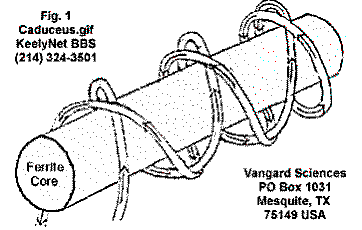
    Dielectric breakdown can be induced by only voltage potential -- making that caduceus/pancake coil seem like a good lead.
    ========================
    Will finish posting parts of this book tomorrow.


    Glad to be enlightened by other sincere perspectives,
    ==Romo
    ========================

    Leave a comment:


  • Dave45
    replied
    Im going to put a copper screen around the coil to see if there is a positive current flowing in the bands that surround the coil


    notice the bands that surround the coil
    Last edited by Dave45; 09-05-2011, 03:39 AM.

    Leave a comment:


  • Dave45
    replied
    my high voltage setup is really simple I have an ignition coil from a ford bronco run to a spark plug I connect the cell to the spark plug when I tap the positive and negative leads to a battery I get a pulse to my cell, the lead from the plate in the cell is shooting a spark about 1/4 inch to a ground wire.

    Ice does not conduct electricity, this proves that structured ice will carry electricity

    Leave a comment:


  • Dave45
    replied
    I should be able to make a poormans superconductor out of a toroid
    Last edited by Dave45; 09-04-2011, 07:41 PM.

    Leave a comment:


  • MonsieurM
    replied
    The Advantage of the Smith Coil is that it has Infinite resonance


    The caduceus coil illustrated in Fig.1, basically consists of ordinary insulated copper wire wound in a double-helix around a ferrite core. THIS COIL HAS REPEATEDLY BEEN FOUND TO VIOLATE ESTABLISHED LAWS OF ELECTROMAGNETICS AND HERTZIAN WAVE THEORY WHEN A HIGH FREQUENCY CURRENT IS INJECTED INTO IT....
    ....First. This apparatus has zero impedance - unlike an ordinary coil. when fed electrical energy the wire in the Tensor coil does not get hot.

    Secondly. It has infinite resonance - unlike an ordinary coil which will resonate chiefly at its natural fundamental frequency and weakly on the second or third harmonic, the Tensor coil is capable of resonating strongly on any number of frequencies randomly spaced in the spectrum. The signal pumped into such a coil strangely enough cannot be quantified (detected) by standard RF (radio frequency) detection apparatus ( see: http://www.energeticforum.com/renewa...tic-field.html .) Many "Ham" radio operators and electronic technicians who have used these coils, are completely baffled by them


    Caduceus Wound Coil Experiments
    Last edited by MonsieurM; 09-04-2011, 04:56 PM.

    Leave a comment:


  • Dave45
    replied
    Originally posted by MonsieurM View Post
    Were the two resonate coils in a Smith (caduceus) coil setup?
    No I was just theorizing about the Don Smith setup, the setup Im using has one coil and one aluminum plate.

    Leave a comment:


  • MonsieurM
    replied
    Originally posted by Dave45 View Post
    Ok if we take the Don Smith coils freeze them in water at low ac voltage it should build a structured path between the coils then when hit with high voltage the voltage will have to follow the structured path, increasing transfer.

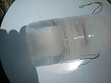
    i'm all for it, in my last experiment with the smith coil wrapped around a plastic needle filled with water hooked to battery , the white part of the structured water looked like a frozen vortex (will have to retest it )....so I do think there is something to it

    the original smith coil link:

    Wilbert B. Smith: The New Science

    Last edited by MonsieurM; 09-04-2011, 04:36 PM.

    Leave a comment:


  • Dave45
    replied
    Ok if we take the Don Smith coils freeze them in water at low ac voltage it should build a structured path between the coils then when hit with high voltage the voltage will have to follow the structured path, increasing transfer.

    Leave a comment:


  • MonsieurM
    replied
    Originally posted by Dave45 View Post
    The high voltage that usually expands in all directions from the coil will have to follow the structured path.

    just like water when it flows...path of least resistance (usually fractal )

    did you take into account gravity when you placed the water when frozen, like your previuos experiment

    Leave a comment:


  • MonsieurM
    replied
    Were the two resonate coils in a Smith (caduceus) coil setup?

    Leave a comment:


  • Dave45
    replied
    Originally posted by MonsieurM View Post
    could you explain the highlighted part , please
    The high voltage that usually expands in all directions from the coil will have to follow the structured path.

    Leave a comment:


  • Dave45
    replied
    Originally posted by MonsieurM View Post
    so you have recreated this with water


    (analogy )
    Yes its a highly efficient transformer because the ice that isnt structured acts as an insulator.

    Leave a comment:


  • MonsieurM
    replied
    Originally posted by Dave45 View Post
    Ok if you have two resonate coils connected using low voltage it should build a structured field between the coils then when used at high voltage the transfer should be increased this needs a lot more investigation I hope people with more knowledge and experience would take a look.

    Dave
    could you explain the highlighted part , please

    Leave a comment:


  • MonsieurM
    replied
    Originally posted by Dave45 View Post
    This means the column we'v been observing is structured water molecules that are conducting and the clear ice around the column isnt structured so it doesnt conduct.
    I wonder what this would do for the Don Smith device?

    so you have recreated this with water


    (analogy )
    Last edited by MonsieurM; 09-04-2011, 04:05 PM.

    Leave a comment:

Working...
X