
Dave45 - I just don't get what you keep preaching to us about the electric field. Can you explain how that would apply to a permanent magnet generator.
I am not saying that you are wrong, I am just saying that I don't see it. You want to change the paradigm that we have already been shown from other great researchers throughout history. Build something and show us so we can understand.
-
magnetic flux does not transfer energy, its the electric field that transfer's energy from one coil to another.Leave a comment:
-
@allen
Thanks for the info. On my youtube I have replicated the Flip Flop, and XEE2 stuff as well. Works well. It would be, at very least, a good test bed, as you say, because I definitely know what occurs WITHOUT the BITT addition, i.e. how X number of bulbs causes X load. In one vid, I underdrive two or three LED AC lamps rated @ 2watts, off of a 3.7 Li-ion, I forget the draw, I think it was optional from 150-240 mA, producing pretty decent light. It's not an overunity thing or even terribly efficient, BUT... it is very unorthodox, and useful to me in that I can charge the battery with solar and it is 4000 ma/H. So you toss it in the sun, and you have AC lighting. Works on a 100' cord.
So definitely that sounds interesting. Are you going to build one? I'm very surprised it has been reported to produce such good results at such a low frequency. Seems most "magic", if you will... or perhaps "high efficiency" (i hate the other words) occurs at higher frequencies. > Thinking such a core would not ring too high in HZ? I do realize that it is about flux paths, that are supposed to make a difference.
CheersLeave a comment:
-
I too have been very interested in the bitt
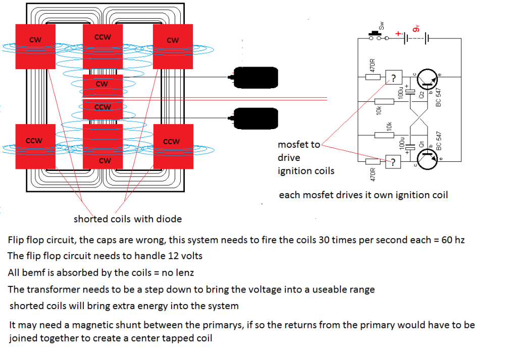
Im not good at electronics but you can get an idea of how it needs to be driven.Leave a comment:
-
BITT draw differential.
@kcarring,
Zero! Thane demonstrates how input mirrors output in the conventional transformer, but output is independent of primary load in the BITT. Woopyjump shows a 1 milliamp increase in his very inefficent fence wire primary draw, to light two 200 milliamp bulbs.
Xee2's simple inverter circuit is generating 120 volt A.C. current from a low voltage D.C. source at very low cost. Connecting the 120 volt transformer to the BITT primary, instead of directly to the A.C. bulbs, allows for a bulb on each BITT secondary. That combination should be 3 or 4 times overunity.
Casting the 1 to 1 Locktite epoxy, supposedly the best epoxy available to bond with iron powder, would allow us to mold the M portion of the BITT transformer core in sandwich halves, to fit the air core holes on three same size pre-manufactured copper wire spools. The flat bar can be molded seperately, and glued to the bottem of the M core. It might be easier to eliminate the middle cutouts and just drill holes at the top and bottem, after hardening, which could be widened or filled in. Casting 3 dowels and 2 bars would be even easier. This approach eliminates the tedious job of wraping, and maximizes the high tolerance of the windings. That's where we can save the missing 1 milliamp Woopyjump looses.
I think Xee2's circuit would benifit from diode protection, because the BITT primary generates BEMF. We can collect this too, and loop it back to source with the simple addition of a capacitor in line with a fast switching diode, or just bleed it through an LED!Last edited by Allen Burgess; 01-18-2012, 01:30 AM.Leave a comment:
-
@Allen
Thanks for your updates. In the Thane BITT inverter what is the differential of the standing-no-load draw vs. the loaded-draw, do you know?Leave a comment:
-
Bitt
Here's an interesting new BITT configuration I copied from "gsmsslsb" off the OU BITT thread. The cutouts in the primary middle leg simplifies the 10 to 1 flux reluctance ratio approach. This looks like a better way then reducing the Locktite to iron powder mix I suggested in an earlier post. Xee2's new inverter circuit might be adapted to power this kind of primary:Last edited by Allen Burgess; 06-21-2017, 11:55 AM.Leave a comment:
-
New Joule thief circuit for 120 VAC LED bulbs that makes it easy to control the current from a 12 volt battery.
video >>>> xee2vids's Channel - YouTubeLeave a comment:
-
Bitt
@SkyWatcher,
Thanks for the video links. Very informing! The major difference seems to be the A.C. nature of Mopozco's secondary output. A requisite for the BITT primary input.
I wanted to add that Thane Heins's BITT primary flux path has ten times the flux reluctance as its secondary path. This means that the cross sectional area of the H bridge would have to be 1/10 that of the outer secondary circle. This results in quite a contrast in proportion for the cold mold. A slim 1/4 inch diameter H bridge would need in a 2 & 1/2 inch diameter secondary. I believe that the H bridge can be thickened to the same diameter as the secondary loop simply by reducing the iron powder to locktite ratio by the same factor of 10. This would allow for the use of wire spools of the same core diameter. Thane measured a COP of 377% in his loaded secondaries with this flux path reluctance ratio.Leave a comment:
-
Hi folks, this would be a nice add-on to that circuit.
Energy Propagation - YouTube
Pulsed DC 2 - YouTube
peace love light
tyson
Leave a comment:
-
Mopozco demonstrates a very simple A.C. inverter circuit in this short 46 second video. It runs off 1.5 volts and a ONE TRANSISTOR oscillating circuit (TROS). He places two ferrite toroid tubes back to back: One, a single wire, simply wound around the outside, and the other, a serial wired bifilar, (JT style). Mopozco calls this a transformer; More aptly a (Transformer Inverter) and it should power the primary of a BIIT, with a recovery circuit and diode protection, much more efficiently then the flip flop version. In addition, he lights a second LED lamp off the JT BEMF. This one's really hard to beat!
TROS - "transformer" - YouTubeLast edited by Allen Burgess; 01-07-2012, 08:25 PM.Leave a comment:
-
Thanks KyleOriginally posted by kcarring View Post
My proposed set up
5 W (Max out 0.28A 18 v dc ) or 10 W (Max out 0.37 A 18 v dc )
1 12v 7 Ah Battery one for solar load
1 12 v 7 ah to supply the SSG JB charger to charge one 60 Ah 12 v battery
1 12 v 60 Ah to supply one laptop desktop , joule ringer lighting
and one 42 " lcd tv.......
Skywatcher mentioned that 5 watts is enough for the 12 v 7ah battery
Will try the Minoly mod for 7ah to 500 Ah charger( Hope Patrick can give the charge time)
5 WATTS SOLAR PANEL TEST 2 080112 - YouTube
5 watts solar panel test 3 080112 - YouTube
totoalasLast edited by totoalas; 01-08-2012, 12:15 PM.Leave a comment:
-
Totalas
How many amps or mA out on your solar panel, can you get, in good sun, versus the input draw on your JB charger? So far my experience with my (weak) JB charger has been that I'd need about 500 of them LOL. I use MPPT instead, until such a time I can have 20-60 amps put to use. I think the JB charger is better suited for small solar applications, not kilowatt installs. Although, during very very low light hours, when nothing else would charge, it has it's place. I like the fact that MPPT can take 20V in, and pulse higher current at 14.5 volts out. Not too mention it takes care of overcharge control, and doesn't send HV into my inverter running at the same time, on the same bank...Leave a comment:
-
SSJB Charger coil used as Driver in magnet Rotor?
Out of Curiosity,
Can we placed an 8 magnet rotor on top of the JB charger 6 coiler while the coiler is charging
or place a dc motor driven magnet rotor on top of the 6 coiler to produce the same effect?????
totoalasLeave a comment:
Leave a comment: