Announcement

Collapse
No announcement yet.

Rebus57 Tesla Device

Collapse
X
 
  • Filter
  • Time
  • Show
Clear All
new posts

  • #61
    Originally posted by Slovenia View Post
    Hi Arend,

    Thanks for stopping by. It's a very interesting link indeed.

    Best Regards,
    Slovenia
    As a reply to your PM, high voltage may have something to do with which coils you wind bifilar. I haven't really looked at this one yet, but there appear to be interesting links to the Kapagen device:
    KAPAGEN, the Tariel Kapanadze's generator

    It seems to me that they key to understanding these devices is to be found in studying the resonances that take place in the system, as I have done for the Kapagen device.

    Since I believe there is a real ether, it helps for your understanding to study the acoustic equivalent:

    Resonance

    Especially this picture is interesting:
    Standing Waves
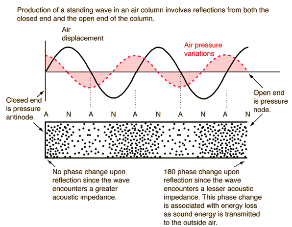

    The air displacement is an analog to "current" or "magnetic component", while the pressure is an analog to "voltage".

    As with musical instruments, you can resonate coils at higher harmonics, higher octaves. Normally, the shortest coil has the highest resonance frequency and the other coils are such that this frequency is also a higher harmonic resonance frequency of the larger coils.

    The interesting thing is that pressure/voltage have a so-called phase difference of 90 degrees when in resonance, so when you have standing waves. So, at the point where you have a pressure node, you have high displacement, while in a coil where you have a voltage node, you have high current. And vice versa, of course.

    If the coils are wound with the same diameter wire and the same core diameter, you can find these nodes / hot spots pretty easily by counting the number of windings, even though you still need to know at what harmonic or octave the shortest coil is resonating, which is usually at the so called quarter wave length, but not always, depending on how it is driven. When this coil is n turns, you have a quarter wave every n turns.

    If you have a coil with a more or less open end, for example only loaded with a small couple capacitor, then at that terminal you have a voltage hot spot, so low current. If the other terminal is loaded, like connected to a transistor, then that is usually a current hot spot, so low voltage. In that case, you have a quarter wavelength over the coil.

    This way, you can see if you can find out at what harmonic the different coils in the system are (supposed to be) resonating.

    Interesting details are bifilar wound coils put in series and coils that are wound in opposite directions on top of one another (clock-wise / counter-clock-wise). Bifilar wound coils put in series give significantly more voltage gain at the half-wave resonance frequency, while opposit wound coils put in series supress the magnetic field and thus prevent current flowing from one coil to the other, which is what is being used in the Kapagen device.

    Comment


    • #62
      Project X Circuit (Upper View Clarified)

      Project X Schematic

      Colorized To Make Schematic Easier to Study & Understand


      Upper Portion of Schematic Color Enhanced & Brightened for Easier Recognition

      Last edited by Slovenia; 11-07-2010, 11:55 AM. Reason: Added a much more enhanced overall schematic.

      Comment


      • #63
        Changes for Project X Circuit

        I posted these for Rebus57 some time back, but they are relevant to the portion of the Project X Circuit I just posted above, so here they are again:


        Here is some more food for thought:

        I was going to take my 2 LED blinky cir,(Ramsey electronic kits), and have it fire two triac's PNP to alternately charge, (tickle), primaries on ferrites and try to use that to make the rest of the device to function properly. The flash rate can be easily adjusted to simulate any frequency. I was only going to use 1 to 3vdc+ through triacs to try to make it function, and more if needed.

        Also I was thinking that a tube like the trigger tube may be required between (Current Collector Tube) and rod to act as a diode, bummer another part to make. Because of using RF no heater is needed in these tubes for flow, cathode will be minus potential, the grid fed by Current Collector Tube and the plate to (Current Collector Rod), also connected to plate/rod are the (Output Tube Circuit) this makes (Output Circuit) isolated from headwaters to prevent any backfeed from shutting down headwaters. This makes more sense and was most likely an integral part of (Current Collector Tube). I told you I was still working this out but it's coming to me. By the way, if you haven't looked already, check out the old pictures of Morays device. You will need to google it, since I don't remember the address. But, you can see the ferrites on one end and output a distance away. If anything, it is inspiring. Also check out some of his tube patents. They are for medical stuff but they are two tubes in one envelope, cool stuff.

        It is my belief that the man made electrons have a much stronger magnetic effect about them than natural occurring electrons. This magnetic component causes opposition to flow and heat build up. This is why I believe it is important to begin with the natural. Along those lines, I was thinking, with a trigger tube like device as a diode between cc tube and rod. It could be fired at any frequency we like while the crystal device runs at a more attainable higher frequency. The rod could run as low as Schuman frequency or whatever testing brings out. Somehow,
        I don't know but I believe the ferrites play a key roll in the collection of proper electrons to be used to ring atmosphere around cc rod. So, this is part of my dilemma. I too would like to artificially induce a high voltage directly to output tube but the tube design is not the same as with proper headwaters circuit so that's why I decided on tickling the ferrite primaries so the rest of device would accept headwaters when worked out and be capable of putting out full power right away.

        The above changes are some of the things that will be in the new drawing and it is the primary reason why my coils are not finished in the picture. The small ones on the wood dowel are mock-ups and the dowel will be replaced with the ferrites. I told you mock-ups are part of my thought process. A lot of times it's easier to really look at something, put it in your hand and let it sit around for a while and think about all aspects of it's function. This I do a lot. My output tubes should be real close. They have an adjustable gap to allow for tweaking and may require a wrap of finer wire cloth over larger cloth. The larger cloth sized for designed amps output, and small cloth to prevent interference with headwaters detector circuit. I don't know only testing will tell. If no one has one working by the time I have time to work on mine I have some really great directions to move forward on and progress looks way more promising now.


        More Changes from Post 10/25/2010 of this thread:

        Rebus57 Additional Information:


        Please note a few changes made that have not yet made it into the drawing:

        1) The bobbin coils on ferrite cores are reduced to only (THREE) per core a center primary and a secondary at each end, all wound with one turn spacing,(about 31t ea.).

        2) The breakdown gaps will be 1/4 in. (.250) diameter hollow spheres.

        3) I settled in on 1/4 in. dia. X 6.000 long ferrites for 100 HZ, (material).
        Last edited by Slovenia; 11-06-2010, 12:27 AM. Reason: Added More Changes from Post 10/25/2010

        Comment


        • #64
          Moray's Tube Patent (2460707)

          As per Rebus instruction, check out Moray's tube patent and pictures of his device.

          Patent 2460707 (1949 Moray Tube Device)

          Free Patent Search Tool
          Retrieving Patent from PAT2PDF.org - Free PDF copies of patents: Download and print!


          Moray Device
          Dr. T. Henry Moray

          The Tom Bearden Website

          Comment


          • #65
            Moray Info for Comparison Purposes & Study

            Information on Moray
            Endless Light - Dr. Thomas Henry Moray

            Information on Moray
            Файлов Архив - Henry Moray - Henry Moray Oscillator Tube

            Moray's Sea of Energy Book
            MEGAUPLOAD - The leading online storage and file delivery service

            Comment


            • #66
              With Regard to Moray

              With Regard to Moray, focus only on the Moray valve & therapeutic device. There are a lot of directions you can go with Moray and we are not intending to get you off topic. The Rebus Device is a mixture of Moray & Tesla, and that's why we focused you on Moray.

              I haven't heard from Rebus in a while and am trying to keep this thread alive for a while longer until he can return and give us some other great details of his device.
              Last edited by Slovenia; 11-08-2010, 08:09 PM. Reason: typo correction

              Comment


              • #67
                T. H. Moray

                Here is some good information from John Bedini about how Moray's device worked
                ETERNAL LANTERNS
                It does describe why the valves worked.
                Last edited by nvisser; 11-08-2010, 08:41 PM.

                Comment


                • #68
                  Interesting, I recieved the same Eternal Lanterns reading material from Aaety Olsen scribe of the Alchemanual, who also spoke highly of John Bedini, I can only assume they are in contact with one another.

                  Comment


                  • #69
                    What happened?

                    What happened to this thread? I had some serious doubts about the circuit, but it was an interesting thread. I was waiting to see where this was going. It has been almost a month and no new posts. Has Rebus given up or just not communicating with anyone?

                    Carroll
                    Just because someone disagrees with you does NOT make them your enemy. We can disagree without attacking someone.

                    Comment


                    • #70
                      Do you realize what you found?

                      This is Tesla's spark gap tube! The one he said he did not perfect yet after his discovery of radiant energy! He Said he was having difficulty getting the tube to work. This has to be the tube he was talking about.

                      The first link is the tube and associated periphery. Hidden in the guise of a Therapudic device... In plain sight.. Figure 8 in the patent. It utilizes static shielding on the left hand electrode. Very very interesting...
                      Last edited by Jbignes5; 12-04-2010, 04:19 PM.

                      Comment


                      • #71
                        Thanks!!

                        Thanks Jbignes5. No, I didn't realize what we had there. Thanks for sharing your insight. Rebus isn't getting back to us now, so this thread is at a dead stand still.


                        Originally posted by Jbignes5 View Post
                        This is Tesla's spark gap tube! The one he said he did not perfect yet after his discovery of radiant energy! He Said he was having difficulty getting the tube to work. This has to be the tube he was talking about.

                        The first link is the tube and associated periphery. Hidden in the guise of a Therapudic device... In plain sight.. Figure 8 in the patent. It utilizes static shielding on the left hand electrode. Very very interesting...

                        Comment


                        • #72
                          Update

                          Hi Carroll, thanks for your interest. Rebus hasn't gotten back to us in quite a while now, so we're at a dead stand-still with this thread. We have a serious electrical guy who has been working with this circuit and thinks it is very viable, but we haven't worked out all the bugs yet. The electrical guy is still playing with it in the background. So, that's where we are. Rebus sounded quite credible when I first found him. I don't know what happened with him. I think he really has the goods but for whatever reason didn't spill all the beans yet. He seemed quite surprised someone didn't take his thread down immediately when we first started it.


                          Originally posted by citfta View Post
                          What happened to this thread? I had some serious doubts about the circuit, but it was an interesting thread. I was waiting to see where this was going. It has been almost a month and no new posts. Has Rebus given up or just not communicating with anyone?

                          Carroll

                          Comment


                          • #73
                            Hi Slovenia, thanks for the update. Let us know if your guy makes any breakthroughs. I still have my doubts about the circuit working like Rebus said it did but I have been wrong before.

                            Carroll
                            Just because someone disagrees with you does NOT make them your enemy. We can disagree without attacking someone.

                            Comment


                            • #74
                              Been Wrong Too

                              I've been feeling bad about starting this thread. It didn't turn out quite like I had envisioned, so far at least.

                              Originally posted by citfta View Post
                              Hi Slovenia, thanks for the update. Let us know if your guy makes any breakthroughs. I still have my doubts about the circuit working like Rebus said it did but I have been wrong before.

                              Carroll

                              Comment


                              • #75
                                Awesome Info & Links!!

                                The links are awesome. Thanks for sharing them.


                                Originally posted by Jbignes5 View Post
                                This is Tesla's spark gap tube! The one he said he did not perfect yet after his discovery of radiant energy! He Said he was having difficulty getting the tube to work. This has to be the tube he was talking about.

                                The first link is the tube and associated periphery. Hidden in the guise of a Therapudic device... In plain sight.. Figure 8 in the patent. It utilizes static shielding on the left hand electrode. Very very interesting...

                                Comment

                                Working...
                                X