
So one of the first steps is to replicate the configuration from the video (only using the phase wire from the ac source) and using the physical earth ground as the neutral wire.
Check if there is any difference in power consumption with 1-wire lamp and with nothing connected to it.
If there is not difference, we can keep on.
-
The video I was speaking about. Phase wire to bulb, neutral AC wire not used. Neutral AC wire is the earth ground.
[VIDEO]https://www.youtube.com/watch?v=idd7iak4VP0[/VIDEO]Leave a comment:
-
Very interesting points.Originally posted by ilandtan View Post
What Tesla discovered is that you only need 1 wire to run any load and you don't need 2 wires. As you know, you can light a bulb with just only the phase wire and the other wire connected to the ground. If you check the power consumption it will be zero because there must be 2 wires connected to register consumption.
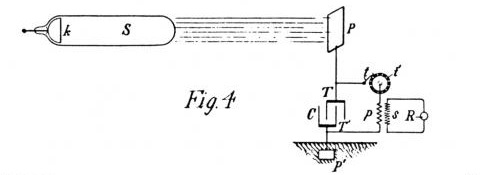
Tesla was doing the same with those circuits. One wire was the radiation received in the plate, the other wire was the earth physical ground. One idea would be to build an DC to AC inverter and use the live wire to connect to the incandescent bulb and the other bulb from the bulb to the physical ground. The neutral wire from the inverted not connected. Of course, the bulb should light. But... that it affects to the battery or not? I mean, using 1 wire depletes the battery or do you need 2 wires to deplete the battery?Leave a comment:
-
Don Smith information is complex because he shows small different details in each of his sources (papers, books, videos...) so you have to read and watch all his information and carefully take notes and organize all. After all that work, you will still need information that Smith doesn't explains. So you will have to check and search in other sources.Originally posted by med.3012 View Post
In the past, there were some videos in youtube that were very good about the plasma ball. The output was small but I remember there was a guy that was capable of lighting a small incandescent bulb with the plasma ball and his own circuit. I tried to watch again that video in the past but I wasn't able to find it. I don't know if the author of that video deleted it.Leave a comment:
-
I agree with you and I have written about that. Why to start with the most complex Smith device? There are other devices that are much more simple. An example is the one I talked about here, that has a big capacitor, some diodes and a high voltage module. There are only 3 components. Why not starting with that?Originally posted by ilandtan View Post
The plasma ball is another example. It doesn't seem too complex to replicate. Smith big device is the most complex of all, so a lot of people will find very difficult to replicate. Why not starting with the most simple ideas? Even the most simple ideas could hide a lot of small details which are critical.
I think one of the big problems is how forums works. A forum I think it's not a great tool to accomplish these kind of organization. A forum is a great tool to communicate, but not to organize projects.
About the plasma ball there is information, but not only in one document. You have to watch the videos, read the documents, and take a lot of notes. There are different informations about the plasma ball IN DIFFERENT DOCUMENTS (including videos). But it's not everything in one document. I have seen the dissasembled receiving part of the plasma ball and it's very simple. If I remember well, there is a bridge rectifier and capacitors in parallel (also the coil). So it doesn't seem very complex to replicate.Leave a comment:
-
I assumed Thomas Ferko's experiment was stepping up the voltage from the plasma ball with a kind of Cockroft-Walton array, similar to what Aether Scientist describes in his post: http://www.energeticforum.com/283380-post79.htmlOriginally posted by ilandtan View Post
Last week, my kids and I did a little Christmas party trick with the plasma ball. One of them put a hand on the ball and joined hands with three of us to make a chain. I was number 4, holding a LED bulb by the threaded socket. My daughter then put her fingers around the bulb's collar above the threaded socket and put her other hand on the metal frame of our coffee table. The bulb lit up. The plasma bulb was effectively the positive terminal, and the metal table a virtual positive (ground).
I believe that what's coming off the plasma bulb is longitudinal electromagnetic impulses. When they meet a capacitor, this longitudinal EM impulses combine with transverse electromagnetic waves to produce useable electricity.
Perhaps the question lies in stepping up the recombined useable electrical charge.
I must cut this post short, but will check back later.
Happy New Year everyone!
BobLeave a comment:
-
I agree with you. I think people try to build the device without fully understanding what is happening or how it works. Another bad point is that people try to build the most complex device at once.Originally posted by med.3012 View Post
I prefer to build simple circuits to understand different phenomena and little by little adding complexity to it.
For example, about Smith we can start building a classic LC resonant tank. Then we can add the L2, and so on...
But trying to build the whole device at once without understanding how it works... it will be very difficult.Leave a comment:
-
Hello and thanks for the message.Originally posted by ilandtan View Post
I agree with you that we have enough resources to try to build anything. I think the problem could be the way we're organized. Here there are brilliant engineers, people with lots of ideas, people with hardware (electronic components). And we agree to openly share the information. So... why we are not getting almost any progression?
It happens a lot in other forums where a lot of people are interested in one topic and there are tools to accomplish it and nothing happens. Someones forget about the subject, others try to do something but they lack of resources, etc... the ending is always the same. Nothing or almost nothing is done. Here, med.3012 is working hard with schematics, videos, etc...
Me, for example, I have ideas but almost zero knowledge about electronics. I have to ask in electronics forums to get, little by little, information. I have not any electronic measurement tools. But I am reading for years about Smith and any space energy devices.
Is there any website where we can organize all the things better?
I know the website Trello, but I don't know if that is good enough.
https://trello.com/Leave a comment:
-
There is not physical capacitor. It seems there is a capacitive coupling. For that reason the capacitor lines are dotted.Originally posted by Jeff Pearson View PostLeave a comment:
-
I know DS couldn't show all his cards, that's probably why you can still find his stuff out there.
Don Smith said a couple of thing that ring in my mind:
1. Something about letting the diodes work for you instead of against you (the wiring components are hidden, but positioned like a standard AC Bridge but of course that wont work)
2. Volts/Amps depends on how you implement ground.
I saw this trying to find other's doing what I was, so I already validated the circuit up to the load, and it appears genuine, the experimenter's previous videos showing supporting pedigree; of course it needs to be tested.
https://www.youtube.com/watch?v=NmKg1Fnnr7s
It appears a plasma ball hooked up to a radiant energy germanium diode bridge. Which makes sense cause it brings together known elements of what other's already know to work. If the device does work, it is a direct validation of Don Smith's plasma globe experiment, and Tesla Patent for Radiant Energy
Leave a comment:
-
if you are interested in plasma ball do it, show your work, if you think Don Smith will show an efficient device for free i think you have to think again about this ... i watched some plasma globe on YouTube but the output is still small ..Originally posted by ilandtan View PostLeave a comment:
-
Why build the hardest Don Smith device
I see from DS pdf, that he has at least two other designs with less complexity, and he claims they demonstrated his theories.
I find the plasma ball, promising as well as simple. Don Smith shows two such plasma energy devices. So it's not a fluke.
The plasma ball embodies the Tesla transmitter resonant coil, totally encased in a retail device, all we have to do is figure out the harvesting side... which is the real trick isn't it? Essentially the part in the PDF that is not Don's actual circuitry, the how to ...turn whatever he devices creates, into usable amps/volts. I would describe Don's resonant coils as pre-1897 Tesla lump coupled "Tesla Coils". Which were RF, resonant, and created scaler waves.
A plasma ball does all that, doesn't it?
So why try to struggle with the tuning and theory of the transmitter side, and just work on the receiver?Leave a comment:
-
Thanks ilandtan
i agree with you, but it's not easy to arrange the work in these forums, a lots of people want a working prototype to tell you succeeded even though if the idea is correct, in my side i believe that the ideas is the most important part in this science, if the idea is understood the problem encountered will be understood also, finally building a device will be a mere question of time.
3 or 4 serious researchers can make a big difference, even working outside the forum will be a good option !
Regards.Leave a comment:
-
Do we work together?
I have never posted before, but I have noticed, a similar situation on these forums, that mirrors work. We have a technical goal, and many brilliant engineers, all span different experience levels and it seems, some have even accomplished the technical goal in the past. The problem with a forum structure, is that the more outspoken contributors dominate the dialog, and the other engineers don't have the same pieces, to assemble sub components to validate function. What is quite possible is that we are are all building are own burgers, and few will turn out a Big Mac, some of us don't even agree we are building a Big Mac.(Sorry for food reference ..LOL). So as a believer in Agile methods let me start by vomiting assumptions, and it might be all wrong, but I assume I will be corrected, and do not fear that. My goal is to start a common point. My requirements are to have a successful, reproducible build that we can all walk away from and say: I did it.
So what is it?
- Assumption 1: Build an over-unity Don Smith Device
- Assumption 2: We all agree to work on the same device
- Assumption 3: We establish a project manager to keep on project, and to summarize progression, enumerate the pain points
- Assumption 4: We post actual schematics, and actual component values.
- Assumption 5: We agree to help each other because we trying to evolve from the (Futile that Tesla himself Lost) information hoarding patent seeking get rich mentality that has crippled our minds, and chained us to the grid.
I think we should start here, because otherwise the information will tend to be a free for all like the internet, and you have to sift for the needle in a haystack. I have seen the Don Smith topic rise and bubble up, I don't believe any of them produced the assumed above.
Respectfully,
XRIXLeave a comment:
-
Amplifying transformer. Smith device?
I think the capacitor on one half of L2 performs the same function as opposite wound coils??Leave a comment:

Leave a comment: