
Originally posted by med.3012
View Post
-
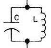
That video shows the basic principle I was speaking about. Exciting the ambient and then absorbing ambient energy with a circuit, in this case the circuit is a LC tank circuit. -
Magnetic Resonance is a Vector
I was out of my depth, couldn't describe it so I intuitively threw out the big word vector to describe the magnetic component... and lookie I have no idea what it means.
Leave a comment:
-
I agree no spark between the towers... They are transmitters. Receivers would be a home with a tuned receiver, a car, a plane. The spark I am referring to is either on the primary and optional spark in the secondary of the transmitter. After 1897 a spark was not required in the L2 because Tesla started using the slow wave helical resonator, the extra coil:Corum. Spark in the receiver was rare in the circuits I've seen and maybe limiters? Spark in the primary of the video was important because it is an electron avalanche. By definition, a spark is over unity because it causes free electrons to flow. You have gain at the spark on both sides on the plate cap, and the ambient is contributing through the casimir effect according to DS.Originally posted by med.3012 View Post
Didn't Wardenclyffe use spark gap in the primary? Tesla coils always used spark gaps did they not? So when I view the Tesla coil circuit, I am looking for a spark gap outside a parallel tank of L1. The Frequency of the tank oscillation will be, when the spark gap is firing generously because at resonance the tank circuit should look like a infinite resistance. The magnetic field in the L1 tank contracting/expanding to a resonant frequency, the spark gap will be discharging at intervals in sync with that frequency (but I don't think it is every-time) It is the push of the swing, maintaining the pressure of the L1, and that's why it needs to be pulsed DC not AC on the primary.
So let me depart from known to my brand of special bus speculation:
I think Tesla knew when he created a RF Tesla transmitter and receiver pair, there was over unity. This would have to be why Don Smith's first experiment was:

Single transmitter, multiple receivers capturing the radiant energy with no degradation. You don't need a Wardenclyffe transmitter. Don Smith sold for 50 bucks a kit that would light a 60W bulb with miliamps of radiated energy.
It seems that in the Don Smith recipe there are some key ingredients:- Electromagnetic Disturbance of the Ambient using HV (pulsed DC)
- Magnetic NOT Electrical Resonance
- RF band of operation preferably above 20K
It would seem Don Smith played by the same rules Tesla had set. Tesla was Don's predecessor so of course, and in the early 1900's you couldn't buy a plasma ball or order a Tesla coil off eBay. Because of Tesla's limitations, his answer was NOT to give the transmitter technology to every man, he would just need to propagate receivers. Or incorporate them into new devices.
Tesla did have to build a large enough transmitter, and he didn't want to pay for the power to generate what he needed to transmit, so he used his earthquake resonance experience to create standing waves using the earth as a cavity to pump his extra coil. We don't need to do that, because Joe Shmo can build 19th century circuits.
We just don't know how to harvest it. --BTW that trick of using earth ground cage thingy worked (not expected).
Leave a comment:
-
Obtaining energy with LC tank from ambient oscillations
[VIDEO]https://www.youtube.com/watch?v=fOkkF4pr23s[/VIDEO]Leave a comment:
-
med.3012
I don't like to answer you without reading carefully all the information you show. As you know, it takes time and I have to answer you other posts from this thread that I still have not answered yet.
So I take note and I will read all the information because you're showing really valuable points. It will take time because I am doing different things at the same time that take too much time.
To start with, I have to finish reading your pdf file. I started about 1 week ago and I haven't finished it yet. I also have some interesting information to show you, but I have to record videos or to write some documents.
As you know, it takes too much time for only one person and I am also studying other fields that are difficult too.Leave a comment:
-
Originally posted by AetherScientist View Post
as you said before it's very hard for someone to do all the work... i published this drawing in my document www.free-energy-info.com/Mohamed.pdf
the E-TBC is able to make a reference voltage proportional to its length using the induced rotating electric field, this field need a kind of capacitive side to create this reference voltage one of Don smith puzzle is solved now, the question is why we use a proportional length between L1 and L2, the reply is given, the other problem is attracting ambient electrons with radio frequency speed ? because we have now this capacitive side inside the E-TBC this device will do this in radio frequency speed ...
another puzzle is electrons spin ok let's take a simple schematic : the following proposed circuit was published in my thread a long time ago :
just remove the green part and place an E-TBC the device will oscillate as its equipped with ordinary parallel L/C tank circuit the following is the scope graph from different E-TBC and you can see the frequency !!!
now how the E-TBC can oscillate even the capacitor don't exist as we know it ??? there's an exchange of electron spin inside this device.. sometimes they spin to make the capacitor ( electric field ) sometimes they spin to make the coil ( magnetic field ) even it's not that simple but finally it's a very simple experiments ...Attached FilesLeave a comment:
-
-
It's needed to perform a lot of simple hard work to better understand the concepts. Then we can add difficult more and more. But starting from zero with the most complex systems (without asking the most simple questions) I think is a way or working very inefficient.Originally posted by med.3012 View Post
I know you're working on your device and you've extracted a lot of useful information. That is very good. But as you know people try to start with the most complex systems.Leave a comment:
-
About resonance I started a thread in another forum and I discussed it. There are different things to have in mind when designing those circuits (resonance, coupling, kind of coupling, etc...). I think there is not resonance between any capacitor plate, but I don't know if there is some specific case where you have resonance between capacitor plates.Originally posted by ilandtan View Post
The exciter I used to replicate that experiment of Smith, was the output of a car's ignition coil. You only need to use the high voltage single wire (don't use the positive or negative of the L1) to excite the transmitter capacitor plate. Then put a dielectric and then the receiver capacitor plate. I didn't use any ground to power the AV plug. Even you can use the output of the L2 Tesla's coil to perform the same experiment. Some people tells that you cannot do anything with the high voltage Tesla's output or the high voltage car's ignition coil. But you can perform work even to light an incandescent light bulb with that single wire high voltage.
That is one question that I asked to some people. How it is possible to light incandescent bulbs using 8Kv 2uF capacitor bank?The main question is how do you drive a 3HP Motor at above 3K RPMs at 20ma (8KV*.02A = 160VA)? When it should take about 1700 Watts (Estimated by 3 HP SPL 3450 RPM U56 Frame 115/230V Air Compressor Motor - Century # B383)?
With 2 uF is hard to light a simple 25 watt bulb. Imagine about 10 x 50 watt (or more), light bulbs. I don't have a definitive answer to that question but I think it's related with frequency. Higher the frequency, higher the amount of energy to use. Smith explains that using 50-60 hertz you can get only about 10 watts of power. Higher the frequency = higher the energy. Also higher the voltage = higher the energy. In Smith's circuit you're not obtaining energy directly from the caps. You're obtaining energy directly from the LC tank. That means that you're also getting the energy from the coil (the L2) and not only from the caps. So you're getting energy from capacitors and coils, that means the LC tank. We're used to see DC charging the capacitor, disconnecting the DC and feeding a load with the cap. Here is different. You use capacitors, but you don't use the same concept.
For that reason I said to build very simple circuits to start understanding basic concepts. Smith's system has a lot of unknow parameters. Not a few ones.
Talking again about resonance, there are several cases too. There are different kinds of couplings, different parameters, etc... It's not just EM coupling between L1 and L2. There is much more.
 Last edited by AetherScientist; 01-02-2016, 05:22 PM.
Leave a comment:
-
Originally posted by ilandtan View Post
i agree with you, but we have to remember Tesla wireless power transmitter for example,

Tesla was able to excite the upper air of the atmosphere, at this level the earth form a kind of capacitor with the air strata, so it's possible to transfer the electric power across a huge distance without problems, not only that ! the power received is more than the transmitted power ...
there's no spark between the towers... only charge tunneling ! the most simple way to attract electrons and make them doing useful work for you is to make them spin, when this is done you could harvest any amount of electric power ..Leave a comment:
-
Originally posted by AetherScientist View Post
i remember something like that was discussed in this thread :
but i didn't followed all the discussion there, the minus of the battery ( or the inverter ) in your drawing have to be connected to the earth , if you are using the main frequency say 50HZ the process of electrostatic induction will not work so good for you... in some country the neutral in electricity company is connected to the earth, the earth ground will let the current to close the loop so you can light a bulb easily.. in some case the power consumption will be small.
i think for this technique to be used successfully we need to follow electrostatic induction rules. one of them using a high frequency, the other is high voltage ( for large power ) and finally using standing waves techniques.Leave a comment:
-
This is one of the first Videos I saw too. I just want to point out. That there is no obvious resonance component here.Originally posted by med.3012 View Post
You simply have Battery > DC Pulse HV Exciter Source > Spark > Anode Plate > Dielectric > Cathode Plate > Spark > Earth Ground.
But I think the exciter wand can be considered a tesla coil device at 8KV?
The main question is how do you drive a 3HP Motor at above 3K RPMs at 20ma (8KV*.02A = 160VA)? When it should take about 1700 Watts (Estimated by 3 HP SPL 3450 RPM U56 Frame 115/230V Air Compressor Motor - Century # B383)?
This is what I'm saying, the work here is the harvest side. Even with the plate setup, they are claiming an order of magnitude power gain, for a load between spark and Earth Ground. NO messing with resonant coupling!Leave a comment:
-
Hello and thank you very much for the video.Originally posted by med.3012 View Post
I performed that experiment without connecting anything to the ground. In the receiving plate I connected a wire to feed an AV plug and it workes as good as usual.
Some in the video (about 55 min) explains about using pulsed DC electricity to perform the same experiment and he explains that it's possible to connect a load between the receiving plate and the ground (something similar like the video of the girl connecting the bulb to the earth's ground).
One of the most interesting questions is if the one-wire electricity consume watts. It seems that it doesn't because for consuming watts you need 2 wires instead of just only one wire. In that schematic it consumes energy because you need 2 wires to transform then into 1 wire. But 1 wire directly seems that it doesn't consume watts
One interesting tests would be to use a battery and connect it to an inverter and use 1 wire and ground to power a bulb and check if there is any difference in power consumption while using or not using the bulb connected to ground. This would be as easy as to connect an amperage and voltage meter between the battery and the inverter.Leave a comment:
 i will show any interesting progress.

Leave a comment: