-
cikljamas, Can you put amp meter to each stingo to measure their individual consumption? -
Yes, I am aware of that. I mean I get better efficiency with two, there should be more with four.Originally posted by cikljamas View Post
What still puzzled me is how come you still have 900 mA input with three stingo. stingo is a load for source battery, I don't get how you get same consumption with three load....Originally posted by cikljamas View Post
Is that the maximum efficiency you can obtain? I found tuning the 500K potentiomer important. Too high value consume more without increasing output current.
How about trying joulethief coil for stingo?Originally posted by cikljamas View Post
You can use your current stingo. Single stingo with single diode recovery, existing coil. Connect the positive of battery to your bed, connect the diode output to ungrounded water. Then see if it do something.Originally posted by cikljamas View Post
JT convert the low voltage to high voltage so it become useable to lit a LED. It allow lower source battery voltage and thus allow more use.Originally posted by cikljamas View Post
This is because I think if we connect the return path to 0V we will still be powering the load even if the transistor is in OFF condition. This normal flow may not have the high voltage of coil collapse current and thus seen as waste if it can not lit the LED.Originally posted by cikljamas View PostLast edited by sucahyo; 12-01-2010, 06:08 AM.Leave a comment:
-
Stingo Sleeper
Hi Cikljamas. The Stingo Sleeper is something I've been devoting much attention to lately. My working one, which I've been using pretty much every time I sleep, uses a transformer, which is optimized to put out 60+ volt radiant spikes. I'm also considering using a toroid coil, which I think will work just fine. It puts out 90+ volt radiant spikes when only powered by 1.5V. Any coil that you can get to oscillate at 3 volts or so will do, except, as Sucahyo has cautioned elsewhere, ignition coils, which tend to give off a masculine energy which induces headaches.Originally posted by cikljamas View Post
Here's two additional threads where we have been discussing the details of Stingo sleeper circuits:
Radiant as electric orgone manipulator
Health Zapper Circuits - DIY and Experimentation
In my setup, I clip the the radiant positive wire to a folded length of aluminum foil, which is submerged in an open gallon jug of tap water. I place this at a distance from the sleeping area. The idea is to create a sink for the male, stimulating energy, similar to that provided by an earth ground.Originally posted by cikljamas View Post
The radiant negative wire clips to the metal of my bed frame...making it a type of antenna, which transmits the relaxing feminine energy. I also keep the circuit close to the bed because I think the coil flux transmits a similar type of feminine energy.
- GodfreyLeave a comment:
-
Hi Sucahyo !Originally posted by sucahyo View Post
But you charge little batteries, when i charge little batteries my
output mAmps are higher then input mAmps, there is no way
that you can achieve this efficiency charging big batteries, because
if that was possible you you would have to to tell us about it long
time ago, am i right ?
I made my measurements today charging BIG batt., here are results :
1. one stingo 900 mA input - 360 mA output
2. three stingo 900 mA input - 410 mA output
3. four coil big JT 900 mA input - 480 mA output
But, considering amount of wire that i spent winding JTs coils and
stingo coils stingo is still better that JT, because as you once said
it is not fair to compare Iowa class battleships and cost guard ships...
I spent a lot of time checking this garbage today, but forget it ,doesntOriginally posted by sucahyo View Post
worth so much effort...
Ok, i will make it but this transformer must be exactly that one thatOriginally posted by sucahyo View Post
is specified or i can use our stingo little toroids ?
And what about these antenas, how it looks like, what to use for
that ?
I made tonight one another little JT, and then i used one long time ago
dead battery AAA (little one), i tested it with analog meter, i put it in
my little magalite torch and all measurements showed that battery is
quite dead, then i hooked my new JT to that battery and measured how
mAmps this circuit drains and it drains 150 mAmps, but i think it just can
not be...No way...So this measurement is just not correct...And i do not
know how to explain this...Led lits very bright, but where from it takes
those joules, it must be some joule thief behind this phenomena...
And since we talk about electronic miracles maybe you are in mood to
explain me just one important reflexion of yours :
Rgds !Originally Posted by Hoppy View Post
No, unless the supply DC voltage was higher than the charging battery terminal voltage plus about 0.6V for the forward voltage drop of the charging diode at any particular point in time.
Hoppy
I see. So that is the reason to use twice source voltage for charged battery.
I think Joule thief would be more efficient if we use source positive as return path. Not 0V ground like many has use.Leave a comment:
-
Well, my last video show that with two stingo I get 540mA output with 600mA input, when one stingo is 330ma output with 420ma input. It is possible I think.Originally posted by cikljamas View Post
Have you sort out the multiple input and output yet? If not then I think it is better to compare it with single stingo.Originally posted by cikljamas View Post
Even with stingo, there is sweet efficiency spot. A spesific potentiometer value that produce most output from input. Different coil or different load has different sweet spot.
You mean you don't get the efficiency he obtained? or worse than your current best?Originally posted by cikljamas View Post
For starter, radiant sleeping aid with battery powered stingo. Use about 45V output:Originally posted by cikljamas View Post
Last edited by sucahyo; 11-30-2010, 06:38 AM.Leave a comment:
-
Hi, my electronic brothers !
Today i ve been working a lot on big JTs, i used old coils from bedini ssg
projects and hooked them on that circuit, and then i tried 4 coil JTs,
efficiency result in range about 1 A is 900 mA input, 500 mA output...
Sucahyo, is that efficiency achievable with four stingos ? When i tried
to drive my three stingos over 600 mAmps input, then i noticed that
efficieny is droping off, but now that i have this accurate results from
JT testing tomorrow i am going to see again how stingos work in that
range, so that i can give precise information on that matter...
I spent even last 4 hours making and testing one JT version with 555
timer but i can not get good output result at all, it must be toroid,
that guy LIDMOTOR showed this http://www.energeticforum.com/attach...1&d=1291092409
diagram in one of his youtube
presentations but he used 2 inchs toroid and i tried with 1 inch toroid
which is big difference...
Sucahyo, i think that now it is time to try stingo for health purposes...
Could you suggest me where to start from ?
What would be the best solution for first health experiment with stingo ?Last edited by cikljamas; 01-15-2011, 02:33 AM.Leave a comment:
-

Yes both are connected to transistor but what I like to point out is to which part the common terminal connect to. I consider it important from health point of view.Originally posted by Farmhand View Post
Thic conclusion came after my own experiment and also conclusion from what other experience. For example exciter, SEC or Aaron version of grey circuit. On those circuit the HV part secondary is connected to the primary via the terminal near the transistor. If you going trough the thread, you will see some replicator mention headache and some do not like being in the same room while the circuit is running.
I hope you understand my point. I hope everyone connect the secondary HV terminal to the terminal near the battery positive.
Stingo drive car coil with pulsed DC. Scope wouldn't be able to tell the difference because there is no zero reference. I use neon bulb and I can have both AC and DC from stingo just by changing potentiometer value or changing spark gap distance.Originally posted by Farmhand View Post
With DC neon bulb will only lit at one side I think everyone agree with this. This video show how I can get DC and AC reading from neon bulb:
YouTube - Description of arc and spark
I use neon bulb terminal as spark gap. Unfortunately my camera quality is not good enough to show the neon bulb electrode. So if anyone can replicate this experiment with better camera, I would really appreaciate it.
Diode at input or even at output do not guarantee DC HV. You can try it with neon bulb as spark. Adding capacitor will produce stable HV DC which may not be appropriate for lifter / TT Brown experiment.Originally posted by Farmhand View Post
I think we only have to watch out for the non electric and non magnetic (non EM) danger. My solution is to amplify only the negative electricity side. Since switching a coil revert the polarity, we amplify the one that connect to battery positive.Originally posted by Godfrey View Post
When neighboor office friend smoke a lot, I run stingo as corona maker during the work hour for a couple of days. Smoke odor usually gone in an hour after running. Stingo had no problem running all of that time. The problem are corona device reliability and over discharged battery..... The health side: no one have problem sleeping during break, friend in the room have less flues when everyone on other room get flues, friend in the room felt better and mention the room smelt better, and no one get headache.
For health consideration, I would prefer if we revert the connection of the car coil primary, using it upside down in your circuit.Originally posted by Godfrey View Post
Some consideration:
- I still fail to make a working high voltage FWBR. I have high voltage diode from Ben that work ok rectifying my car coil output but will not function as FWBR. neon bulb still lit on both direction on FWBR output.
- I think one source battery design is easier
- I prefer to combine the HV output after a diode. A diode for each HV output. Combining before the diode may reduce the current going to the load since they will go the the other car coil instead.
- Since the load is low impedance relate to HV output. We may end up charging the load with only 25V or so instead of >1000V. But this should be a good way to desulfate a battery.
I don't think I can make this circuit because I don't have high voltage capacitor. I made a low voltage ceramic cap explode once.... If I replicate I will be using my latest combiner with high voltage diode and cap.
I hope someone can test high voltage FWBR with a neon bulb.
He die at old age isn't it? 70 or so.Originally posted by Guruji View Post
For sharp senses, where did you read that? I highly believe that he already a sensitive at young age, already gifted as child, boosted at age 17 or so. If you ever read Garry Vassilatos book, Tesla is mentioned to be able to see a stream coming from a coil. Not spark or corona but white smoke that behave more like an aura than a real smoke.
Other people die at old age is Mooray and Rife. Both use special vacuum tube.
I highly believe electronic circuit can produce something other than electric or magnetic, that can influence people in a good way or bad way.Last edited by sucahyo; 11-30-2010, 02:17 AM.Leave a comment:
-
Tesla in old age
Sucahyo you mentioned Tesla about that he was not affected by radiation. Maybe not but I heared that he had a type of sickness before he died that his senses became very sharp that everything got amplified. If one imagines this type of desease that even other people suffer it is hell on earth.Leave a comment:
-
Originally posted by cikljamas View PostRadiant as electric orgone manipulatorOriginally posted by Farmhand View Post
Health Zapper Circuits - DIY and Experimentation
Guruji, good luck with the toroid, it should work with an adaquate number of windings. Good point in bringing up the question of radiation. I think the qualities of what's emitting from a spark gap are going to hinge on frequency and pulse-width among other factors. I'm glad to see people being aware of and concerned for what is being put out in theirs and everyone Else's environment as a direct consequence of their experiments.Originally posted by Guruji View Post
Thanks Jbignes5, for the information!Originally posted by Jbignes5 View Post What you propose w/o the trannies probably can't be called a Stingo anymore
You make some more good points regarding radiation concerns. Eventually, we're putting together practical devices that will be turned on for long periods and the consequent radiation could potentially be hazardous! This deserves serious consideration in the design details. An idea which has been on my mind for awhile now, is to run one oscillator/coil in one direction and another in an opposing one, fairly close together as a potential solution to cancel out such electromagnetic radiation. Might work...haven't tried it yet.
Right on, crackahcrackah!Originally posted by crackahcrackah View Post
Thanks for posing this, SeaMonkey...and finding more examples of oscillators not needing caps to boogie!Originally posted by SeaMonkey View Post
7imix, enjoyed your Walwart transformer and toroid videos. Yes, I've noticed the potentiometer tuning can require very fine adjustment too. Good ideas!Originally posted by 7imix View Post
Really cool effects you're getting with that slayer exciter coil and the neo magets, Jiffycoil!Originally posted by Jiffycoil View Post
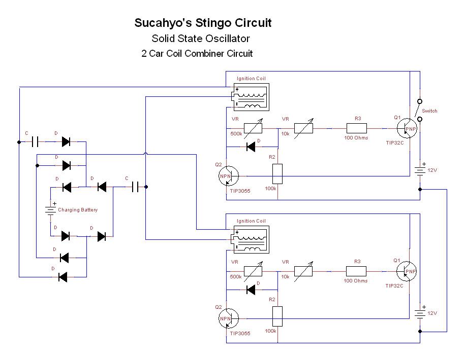
That's an interesting proposal and very relevant to my present concerns as to how to adapt two car coil driven Stingos to your combiner. Whether one is using it as a zapper or just to charge batteries, the effect of one operating in the nearby environment!Originally posted by sucahyo View Post
@Sucahyo
I usually don't run a design by you before I jump in and construct, but this one's complex, so I'd appreciate your feedback. As you can see, my choice of using 2 matching car coils complicates the soup because I'm trying to exploit the HV output produced by the secondary, so here's my modified combiner schematic:
Wadyahthink?
- GodfreyLast edited by Godfrey; 12-01-2010, 05:37 AM.Leave a comment:
-
Sucayho I looked at your diagram two posts above, but I don't understand because both side's of the car coil primary are connected to transistors
My Stingo energises the coil with AC, I think, there are no diodes between stingo and coil, I might be wrong but the scope trace looks AC to me.
I have used a diode so the coil is pulsed only one way but it would still be connected to a transister as far as I can tell.
But I do understand what you are saying about the male and female energy.
I will keep it in mind, and I think pulsing one way is the best for radiant energy.
Thanks for clearing up what you were saying for me, I appreciate that, sometimes i'm a bit "parallel" to what others are thinking. Putting our thoughts in "Series" could be very interesting. 
Thanks Sucahyo
Leave a comment:
-
Here is the video showing how the input current and output current change when the number of running stingo change:
YouTube - stingo combiner, 1+1Last edited by sucahyo; 11-29-2010, 06:24 AM.Leave a comment:
-
Thank you. that is my concern. You seems to connect common terminal to transistor.Originally posted by Farmhand View Post
I highly believe that connecting the common terminal to transistor amplify male energy. While this energy can provice stimulation to phyisics, eliminate parasite or reduce pain, too much can do harm to the point of serious mental or even physical problem in the long term.
Here is what I think:


So blown lightbulb do not perform the same as very small spark gap?Originally posted by Farmhand View Post
Yes, that would be coolOriginally posted by Farmhand View Post.
About this I still not clear. I can only answer if you use neon bulb as load for each of three stingo.Originally posted by cikljamas View Post
I still never do efficiency comparison between single and multiple stingo with the latest combiner. It is possible that latest combiner give different efficiency figure. But I still get output in proportion with the number of running stingo. I will make video for this later.
But, what make me puzzled is you don't have triple output. When I mean 900mA, it is 900mA for all three of them, where each still consume 300mA. But combining three 180mA output give me at least 500mA. And it do not matter if I do not use stingo.
How come a single running circuit can consume 320, but two running circuit do not draw the same? I think your other circuit is dead. We can find that out by letting each stingo power different load. A load for each stingo. Three neon bulb for three stingo, separate from each other.
Interesting. How do that compare to the efficiency reported by the circuit designer? Do you achieve similar efficiency as other big joule thief replicator?Originally posted by cikljamas View Post
With similar recovery method the advantage of stingo is only with low impedance load. If you use my cap isolated FWBR method, you will have better efficiency than many.
Do you use the same coil for stingo and joule thief? it can only be equal comparison if you compare using the same primary.
I still never try to improve stingo efficiency with capacitor since I only have one multimeter. So standard stingo can be easily beaten by a carefully tuned circuit.Leave a comment:
-
Hi Sucahyo !Originally posted by sucahyo View Post
I just answered to you in thread "This is it", and i forgot to thank you for
that jeanna hint...I hope i am going to get that diagram, one way or
another, it must be something very good if you suggest me his variation of
JT...
Regarding stingos, i spent a lot of time a day before yesterday checking
stingo by stingo, and they all work good, that is how i noticed that weird
phenomena that i wrote about in my last post in this thread...
So, as i am explaining in this video (i ll give the link here too), it is about
adjusting pots, nothing else, if i decrease resist. mAmps go up, and vice
versa, so that is whole story about that...
And after i finished shooting of this video i tried to charge cell phone batt.,
but it seems that this big JT is not good for that purpose, but for charging
other big batt. is very, very good...I just tried to decrease all pots to the
minimum and the result is 310 input, and 190 output, and the best result
with stingo in this range was 310 - 140...
So, i am very curious what you are going to comment on this efficiency...
For little batteries STINGO is still the best choice, and for big batteries
is very, very good...
Oh, i almost forgot the link for video :
YouTube - Joule thief vs stingo
Rgds !Leave a comment:
-
Sucahyo
The common ground on the car coil you mean ?Thanks. To which part the common negative connect to?
The stingo is connected to the primary of the car coil, the charging output is from a diode on the Common negative, yeah!, oh! I see what you were asking now I think, yes and the negative of the charging battery go's to the positive of the source, yep. And another wire come's off the common negative as well to one side of the conical winding with the small spark gap, and the other side conical winding is connected to the HV output, the air gap between them.
I'm sorry I was confused.
Yeah tried the blown bulb but the one I have only has a small break, the spark gap has to be very small to work when charging a battery minute actually, but if you use a collecter coil you could forgo the regular battery charging and run the sparkless gap for lights and health.Great . Have you try dead ligth bulb too? What is the nuisance of the spark gap?
I wouldn't mind seting up something that looks fancy with some lights, something really efficient, to run all the time with a sall solar panel or something to keep it running. Would be a good talking point.
Cheers hope I explained that better this time.Leave a comment:
This forum is preserved as a permanent archive. The community continues at eMedia Press.
- If this is your first visit, be sure to check out the FAQ by clicking the link above. You may have to register before you can post: click the register link above to proceed. To start viewing messages, select the forum that you want to visit from the selection below.



Leave a comment: