Announcement

Collapse
No announcement yet.

Gray Tube Replication

Collapse
X
 
  • Filter
  • Time
  • Show
Clear All
new posts

  • bmentink
    replied
    I have re-done my schematic as per your corrections.


    There is still some confusion as some of the diagrams posted show the anode of the HV diode connected to the center pole of the ignition coil, and others like your correction showing the cathode. You can see why I am confused, you are not consistant. i.e the pdf you posted: http://www.energeticforum.com/redire...ytubeworks.pdf shows the anode connected.

    Please look at the drawing and correct anything you think is still wrong.

    Questions:

    1. How do you charge C1
    2. How is L2 pulsed
    3. When is the switch operated.

    -------------------------------------------------------------------------------------------------------------------------------------------------------------------------------------------------------------------------------------------

    PS: Your "peaking" caps in your previous posts on your "silent plasma" have a + - marking. This is incorrect, as the cap is across the inductor, the cap has AC passing through it, not DC.
    Your "silent" plasma is just an AC arc which is a lot quieter than a DC cap discharge one ...

    Your "green" discharge is just a higher energy discharge. I can get the same if I discharge a spark in air with several uF of capacitance at 5kv with platinum electrodes. (no copper in sight ..)
    With the same high energy discharge I can "pop" neo magnets upto the ceiling .... nothing special there, just high energy for short amount of time ...

    I can get fluorescent bulbs and normal neon's to flash green even purple instead of the usual orange ... these are all indications of a higher energy discharge pulse raising the gas in the vicinity to a different isotope level.

    What will be "special" is producing continuous high energy pulses from the grids ..... I know how to do that with special techniques .... and they don't involve diodes.
    Even if you are getting the "effect" you desire with the small window before the diode blocks shut, you won't get significant power that way continuous, the average power is too small ...
    The key is getting more energy into the spark for a longer time .... that opens the door to the high current ....I know how to to that.

    The power will then be applied to a resonant transformer modulated to the required load frequency. .... task complete ......

    Aaron, I do not just talk ..... I have been experimenting on this for a long time. I am talking about "practical" hands on experiments. Once I have verified my latest circuit, I will post the schematic on-line and you
    will see how I do continuous high energy pulses .... I havn't posted any circuit up to now, because I want to post a complete working circuit that everyone can replicate, not some half-circuit's that are misleading and incomplete.
    Hence all the questions from me .... I am trying to get a complete circuit for your setup .....none of your circuits are complete, have component values, construction method's etc that everyone can duplicate ...
    Attached Files
    Last edited by bmentink; 10-26-2015, 12:46 AM.

    Leave a comment:


  • Aaron
    replied
    How the Gray Tube circuit works

    Originally posted by bmentink View Post
    No, you are incorrect, I do not dispute that ..... you may be right, what I do dispute is your contradictory statements you make.

    You stated:


    Which means you have the connection like this:


    That means that you will have a NEGATIVE voltage on the cap not POSITIVE, and you will get an arc across the gap. Do you dispute that as well?

    Maybe it's just the way you communicate that is the issue.
    I know what you mean, that but is not what I'm doing.

    This is my circuit, cathode is at the high voltage and the high voltage is POSITIVE.


    The diode there serves a DIFFERENT purpose than placing the diode between the HV source and the HV rod.

    The diode you show in your diagram is indeed how you want to place it IF the HV is negative, but again, that is not what I'm doing or showing.

    This pdf might help you: http://www.esmhome.org/library/edwin...ytubeworks.pdf

    And this:


    Attached is the circuit you posted, but with corrections.

    I'm using my CDI plasma circuit as the HV source, which is the plasma effect, which is used to initiate an even bigger plasma effect in the motor's inductor.

    1. When the c1 is switched to the primary of the ignition coil, the HV POSITIVE leaves the ignition coil and does NOT jump to the LV rod yet. It finds ground backwards through the diode at the top of C1 just like I posted in my basic plasma ignition schematic.

    2. The very moment that it jumps backwards through that HV diode, the reverse rating is met and it shuts off and is then reverse biased.

    3. The HV discharge is not completely discharged, only a small percentage went backwards through the diode and when it shuts off, it has to find the next lowest resistance path to ground. The next lowest path to ground is backwards through HV diodes at the LV rod side, backwards through those diodes, through the cap and back to ground. In other words, the cathode of D2 IS the ground for the HV discharge. When the HV discharge goes across the gap from the HV to LV rod, that pathway is ionized and then the rest of the charge in C1 will go through the diode over the HV rod to the LV rod causing the plasma effect at that gap.

    4. The moment the discharge hits the cathode of D2, D2 is then reverse biased and shuts off - so this discharge has to find another path to ground, which is over to the grids through the inductor and back to ground.

    5. The moment the discharge is turned away by D2 and jumps to the grids, the pathway between the rods and grids is ionized making it very, very conductive and C2, the cap supply on the LV rod side will go through the diode and over the gap to the grid, through the inductor and back to ground. The C2 capacitor current moves at a negative resistance from ground up through the inductor, to the grids and back to the rods.

    This is how it works.

    Instead of starting the HV discharge as a cdi plasma ignition diode, you can have a power supply charging up a 4000-5000v cap at a couple uf's, switch it into the circuit and it will jump across to the LV rod slamming into the cathode of a diode or triode that is in the circuit there in front of caps or battery banks. That D2 will then be reverse biased and that conventional hv cap discharge will then go to the grids, thru inductor and back to ground. Then the cap bank or battery bank behind D2 will then move through D2 and over the ionized pathway to the grids, thru the inductor and back to ground while the current from the cap bank or battery bank behind d2 moves from ground up through the inductor, to the grids and back to the LV rod.

    Or, you can keep the HV cap in the circuit and then put a commutator switch between D2 and the cap or battery bank there.

    From my experience, the plasma discharge ionizes the gap way better than a conventional cap discharge making it much easier to have a lower voltage higher current source jump that ionized gap.


    Attached Files

    Leave a comment:


  • bmentink
    replied
    Originally posted by Aaron View Post
    You continue to ignore the indisputable fact that the diode is NOT in reverse blocking mode until there is more voltage at the cathode than the anode in order to cause it to block the positive voltage. Until that happens, the diode is a complete path to ground whether you believe it or not.
    No, you are incorrect, I do not dispute that ..... you may be right, what I do dispute is your contradictory statements you make.

    You stated:

    The cathode of my diode on the ignition coil is at the HV because the HV is POSITIVE. You have it backwards.
    Which means you have the connection like this:


    That means that you will have a NEGATIVE voltage on the cap not POSITIVE, and you will get an arc across the gap. Do you dispute that as well?

    Maybe it's just the way you communicate that is the issue.
    Attached Files
    Last edited by bmentink; 10-25-2015, 07:05 PM.

    Leave a comment:


  • Aaron
    replied
    diode test

    Originally posted by bmentink View Post
    No, you have it backwards. If you have an AC signal from your ignition coil and apply it to the cathode of your diode you will get NEGATIVE voltage out of the anode ... if you cannot get such a basic electric principle ... then everything else you say I just can't believe Sorry!


    .. and yet still no working replication producing power .....


    I will try and explain it to you. If you connect one end of a resistor to the positive of a battery and measure voltage either side of the resistor relative to the negative of a battery and the other end of the resistor is open, you will not get any voltage drop across the resistor because there is no current flow, i.e the voltages will be the same. The same if you have a diode connected by the anode to the positive of the battery with the other end floating ....

    No, I have it perfectly straight and I'm speaking from experience and I can prove it. You continue to ignore the indisputable fact that the diode is NOT in reverse blocking mode until there is more voltage at the cathode than the anode in order to cause it to block the positive voltage. Until that happens, the diode is a complete path to ground whether you believe it or not.

    If you have the anode at the hv output, then you have NEGATIVE hv from the coil because the diode's function is not to conduct the voltage from the coil over the gap to the ground, it's function is simply to get the HV to jump to it so that AFTER it jumps to it, then it will shut off. That isn't even debatable. You're not trying to understand what is going on here - you're trying to fit it into your present understanding. It is BACKWARDS from what you think is happening.

    If it worked like you believe, then the diode would NEVER shut off and the HV would completely discharge through the diode and would never go to the grid, which defeats the entire point and the plasma effect would never happen.

    No working replication producing power? My motor in that youtube video is one of the few that has ever shown a running motor using this principle. Whether it is generating anything or not is irrelevant. It is to prove a concept shown in the "Gray Tube."

    You are incorrect. We are talking about a diode and not a resistor. With a diode, you will show EXACTLY what I already described. Please stop trying to figure it out with what you think will happen - just do the experiment.

    [VIDEO]https://www.youtube.com/watch?v=HK9ZoUYYWZM[/VIDEO]

    Try this...

    Put two 12 v batteries in series and get a 3rd 12v battery. Connect the 24 volt series battery's ground to the single 12v battery ground. Between the terminals, you will then have 12v potential difference as shown in the diagram I showed before.

    Now, place a diode like a 1N4002 with the anode on the + of the 12 v battery and keep a volt meter on that single 12v battery. Now, tap the 24 volt series battery + to the cathode of the diode on the single 12v battery that shares the same ground as the 24v series bank. You will see the single 12v battery voltage jump up. That is because everything I have been telling you is what is actually happening and what you believe is the case is actually incorrect.

    The ignition coil hv is POSITIVE and is able to go backward through the diode just like the experiment I posted above. If you actually do it, you will see that too and that should wipe away any beliefs to the contrary because documentation beats conversation and the experiments show you the truth. You cannot mistake the polarity of the battery example I describe in the previous paragraph and it will put all the misconceptions to a rest. I have done that experiment and again, am speaking from experience and not just what I think should happen.

    Leave a comment:


  • bmentink
    replied
    Originally posted by Aaron View Post

    The cathode of my diode on the ignition coil is at the HV because the HV is POSITIVE. You have it backwards.
    No, you have it backwards. If you have an AC signal from your ignition coil and apply it to the cathode of your diode you will get NEGATIVE voltage out of the anode ... if you cannot get such a basic electric principle ... then everything else you say I just can't believe Sorry!

    I showed this years ago and still teach it today.
    .. and yet still no working replication producing power .....

    I don't know what you mean by seeing a voltage difference if there is current flow.
    I will try and explain it to you. If you connect one end of a resistor to the positive of a battery and measure voltage either side of the resistor relative to the negative of a battery and the other end of the resistor is open, you will not get any voltage drop across the resistor because there is no current flow, i.e the voltages will be the same. The same if you have a diode connected by the anode to the positive of the battery with the other end floating ....

    Leave a comment:


  • Aaron
    replied
    Gray Tube replication

    Originally posted by bmentink View Post
    Yes, exactly current (electron flow) moves from whatever is more negative to whatever is more positive .... I do UNDERSTAND as I am an electronics engineer of some 45 yrs experience.

    So where is the WORKING Gray tube replication that Bedini has running, if he knew it all we should be able to see the video of his version running.

    Like I said above current moves from negative to positive, exactly the opposite of the depicted current direction in the picture above.

    It's not firing because it is reverse biased. So if Gray was using diodes, why does he show a triode in the specific location of the LV rod and he has diode symbols elsewhere. I am referring to the patent drawings, are you saying they are false?

    I will ask you one thing, what is the polarity of the HV diode you have connected to the ignition coil? It looks like the cathode is connected to the HV terminal of the coil, which makes your HV NEGATIVE and the reason why your diodes on the LV side pass current. I might be wrong as it is hard to see in such a grainy low quality video.


    I have tried both.


    You will only see a voltage difference if there is current flow.

    My setup is exactly the same as yours, apart from I am using a flyback transformer with built in HV diode as my HV source and different diode for the LV side.

    You have made me think about my LV diode though, and I just went and checked it and found it has indeed blown open circuit. EDIT: Actually it is ok, just my meter was showing it high impedance both ways, but it works in circuit one way, not the other. It must have several diodes in series internally and my meter won't pick that up as a diode.

    .. so in an effort to duplicate your setup further I will replace it with exactly your diode arrangements. After all, If someone cannot duplicate the effect you have, then your experiment becomes invalid .... it's in your best interest for me to get exactly what you are seeing ..

    PS: How are you triggering your spark?
    John Bedini & Ron Cole were welcomed into Gray's lab to examine his tube and motor setup. The diagrams you see from John pretty much match the patent, but the patent has a few things missing that were discovered to be misleading. Those missing details are now known such as the spark gap overshoot that is intentionally drawn wrong in the patent, etc... John utilized some of these principles of "splitting the positive" in other circuits over the years.

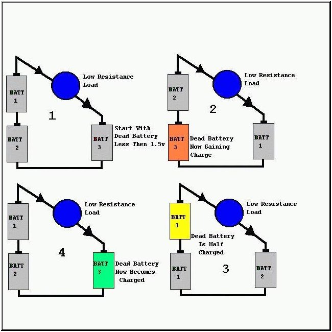
    The picture I posted shows exactly what I said. When the load of the bulb or whatever other load is between Battery 1 and 3, the current is moving from the positive of batt 3 TOWARDS battery #1 through the load. The arrows you see on the circuit are not the current direction that is the direction of the voltage - not electron current.

    A diode opposing a HV source is not reverse biased until AFTER the reverse rating is met. When there is nothing moving into the cathode of the diode it is a complete open path to ground for the HV source. That is just how diodes work contrary to what is commonly believed. It is only believed to be a blocking diode but it doesn't block anything until AFTER the HV jumps into the cathode. There is perfect continuity in the connection between the ground of the LV source and the cathode of the diode. That means it is wide open and is a path for the HV to find ground through the diode, through the LV source and back to the ground that is shared between the LV and HV source.

    In the Gray circuit, the HV cap on the HV rod side is constantly being charged by the power supply. It is triggered when the commutator puts a diode or triode into the circuit - then the HV jumps to the LV side before jumping to the grids.

    In my circuit, the diode is constantly in the circuit and I'm triggering it on the HV side when I drop the cap to the primary of the ignition coil. It can be done on either side. If I had it scaled up, I would trigger it behind the LV diode/triode just like Gray but I'm using a down-scaled version.

    The cathode of my diode on the ignition coil is at the HV because the HV is POSITIVE. You have it backwards. You have to understand how the circuit works and as far as replications, there are several that work because they did it exactly like I did.

    And replications of the ignition circuit - my version of the plasma circuit has been replicated by at least hundreds if not thousands of people around the world proving the principles of the diode like I have been describing.

    I showed this years ago and still teach it today.

    The HV output has 2 paths to ground.

    1. The low resistance path to ground is backwards through the diode, which is NOT reverse biased until AFTER the HV hits it. HV hits the cathode goes through the cap back to the HV ground, which is shared by the LV cap.

    2. AFTER the HV moves backwards through the diode, the diode is then reverse biased only AFTER it is hit with HV and has now where to go but to another path to ground. The second less restrictive path to ground is over the gap back to ground.

    3. After the HV moves over the gap of the plug, it is ionized enough to be conductive enough so that a low voltage source like the cap can move over that gap. When the gap is ionized, what is in the low voltage capacitor (low compared to the HV output of the coil), the voltage of the cap moves through the diode and over the gap back to ground.


    I don't know what you mean by seeing a voltage difference if there is current flow.

    The test I'm talking about is not to test just the diode.

    For example, take a capacitor and charge it to a few hundred volts and then from the positive terminal, place the anode of a diode on there. Now, place the negative of a voltmeter on the negative of the capacitor and the positive of the voltmeter to the cathode of the diode. You will see the voltage of the capacitor minus the diode voltage drop. If you have a microwave diode and you put it on a battery, that isn't enough voltage to open the diode.

    What that means is that the diode is not blocking anything when it is just sitting there connected to a LV rod. It is a completely wide open path to ground. If the gap between the rods is closer than the gap between rods and grids, the gap at the rods is the lower resistance path to ground.

    That means that if the diode is put into the circuit by a commutator or if it is already there and you discharge HV to the HV rod, the HV will jump the gap right into that diode since it is open and not reverse biased and will find its way back to ground.

    It is only reverse biased AFTER it is high with high voltage and the cathode becomes higher voltage than diode, only when that happens will the diode be reversed biased. But until that happens and the cathode is untouched by any HV, it is a completely open path to ground for the HV.

    This motor in this video works because what I'm saying is 100% accurate.

    I'm just posting the facts of EXACTLY what I have done and exactly what others have to done to replicate my experiment. Everyone with a plasma ignition circuit that works with my method already has this miniature Gray circuit, they only need to put in an inductor between the spark plug gap and ground.

    In this video, you can see how I trigger it. A reed switch is switched by a magnet on the wheel. That reed triggers and SCR to drop a capacitor across the primary of the ignition coil and you can see the basic ignition circuit above.

    [VIDEO]https://www.youtube.com/watch?v=nxsoze9CZ9E[/VIDEO]

    What I also have is a separate power supply charging a cap bank that you see on the left side in the video. That is my "booster cap" setup that is in parallel with the gap with the coil in series with that cap bank. So when the front side ignition coil plasma discharge ionizes the gap, that cap bank discharges through the ignition coil in its negative resistance mode making the cap discharge not into a positive resistance but it is getting sucked out at a negative resistance pushing the power density abnormally higher than it normally thought possible.

    I'll do what I can to help you get success with your experiment, but please understand, and with all due respect, you did not learn this reverse diode method in school or in your experience and it is very counter intuitive. But once you see that my explanation is accurate - not just by me saying it but by you experiencing it, then everything else will fall into place.
    Last edited by Aaron; 10-25-2015, 03:20 AM.

    Leave a comment:


  • bmentink
    replied
    Hi,

    Yes I have already ordered super-fast recovery ones, I will be building up a string out of those plus a string out of the 6A100 Aaron is using to compare ...

    ... then, I will be setting up my Thyratron and switching circuit and compare that as well.

    I will post results here.

    Leave a comment:


  • BroMikey
    replied
    Originally posted by bmentink View Post
    Actually my diodes are rated at 15kv 500mA continuous 35A peak, the current rating is a problem though.

    I will get better diodes. But like I edited above, the diode is fine, just my meter could not read it like a normal diode.
    Yes i would do it just like he is for several reasons.

    (1) the MOT max surge 35amp is under normal conditions of minuscule

    amounts of power and to represents a restriction Aaron will not encounter

    with his string


    (2) The 6A10 common general purpose diode has a max surge current

    of 400amps under normal running conditions that are 30X power levels to

    one of those cheap-O MOT diodes.


    (3) Should the current of a MOT diode go above a tiny bit in a short

    pulse the resistance value climbs enormously.

    In my view because this experiment has been done time and time again then

    you will be needing to buy some diodes to make a string, why not buy

    fast diodes of even ultra fast for nearly the same price?

    Then you can add to this work, in my opinion.


    If you want numbers to get the fast ones, Aaron and others have posted

    these before somewhere. We can get a good number for you. The thing

    I found out was that when I replaced my slow diodes with fast ones I

    ended up gaining almost double.

    Aarons talking 5000volts and MOT diode run at 2000volts.

    Herehttp://www.diodes.com/_files/datasheets/ds28009.pdf


    http://www.e-edi.com/pdf/diodes/2CL2.PDF


    I learned that these pulsing circuits work better when resistance from

    component heating is not present. Aaron's string rating is some outlandish

    figure if you want max data.

    I'm not telling you what to do, just that diodes have been a learning

    experience for me with these plasma energy tools.

    Once you go with fast or ultra you will never look back.
    Last edited by BroMikey; 10-24-2015, 10:54 PM.

    Leave a comment:


  • bmentink
    replied
    Originally posted by BroMikey View Post
    The MOT diode is good for 100ma? At 90 percent? Some really small figure.
    Actually my diodes are rated at 15kv 500mA continuous 35A peak, the current rating is a problem though.

    I will get better diodes. But like I edited above, the diode is fine, just my meter could not read it like a normal diode.
    Last edited by bmentink; 10-24-2015, 09:25 PM.

    Leave a comment:


  • BroMikey
    replied
    Originally posted by Aaron View Post

    What you have to understand is that this is about potential differences and not polarities.

    Bedini has shown this for over 20 years online:

    Again, it is about potential differences and not polarities. That is what will help you understand what this is about.

    You should try that 3 battery experiment for yourself ........................This is identical to what you are looking at in the Gray Tube.

    Can you post a diagram of your setup?

    Of course the commutator controls the pulsing of the coils.

    That is what makes the coil pulse fast and not the switch because the switch is only a small fraction of the speed that the LV discharge happens at - they're not even close to the same.

    Originally posted by bmentink View Post
    ............................. I am an electronics engineer of some 45 yrs experience.


    So where is the WORKING Gray tube replication that Bedini has running, if he knew it all we should be able to see the video of his version running.


    I might be wrong as it is hard to see in such a grainy low quality video.


    ............... I just went and checked it and found it has indeed blown open circuit.


    PS: How are you triggering your spark?
    Thanks Aaron for this refreshed copy and repeats. This stuff does take

    time to soak in. Back in the 60's I remember seeing all of the Tesla books

    left over for the early 1900's til they were thrown out like trash in the

    dumpsters.

    The battery experiment is an experiment that even the most experienced

    will never consider. I see your video and it looks like you are using a mini

    Bedini wheel? made of acrylic (SSG?) For your energy pumping and some

    might call that a trigger? I know the SSG circuit is DC but it is pulsating

    DC so maybe this is what people are thinking.


    Also the microwave diode is only good for a 2000 volt oven transformer.

    I know the rating on a MOT diode says it is higher but this is common to

    select a higher rating for any job.

    Also if I were Bedini I would not want to be responsible for posting a

    potentially lethal setup, telling everyone to go for it. I wouldn't do it.


    Even the most experienced are afraid of HV.

    Your diodes are 1000-1200volts each multiplied times how many ever diodes

    at and amp handling capacity that far exceeds the MOT diodes.


    Of course you know all of this Aaron, thanks for sharing this thread.


    The MOT diode is good for 100ma? At 90 percent? Some really small figure.
    Last edited by BroMikey; 10-24-2015, 09:13 PM.

    Leave a comment:


  • bmentink
    replied
    Originally posted by Aaron View Post
    You have two opposing dipoles - one is high voltage and one is low voltage. When the HV moves towards the + of the LV source, it is finding it's path back to the HV ground through the LV source and back to it's own negative. The current is moving from the HV source negative TOWARDS the negative of the LV source through the LV source and out of the LV source positive back TOWARDS the positive of the HV source.

    What you have to understand is that this is about potential differences and not polarities.
    Yes, exactly current (electron flow) moves from whatever is more negative to whatever is more positive .... I do UNDERSTAND as I am an electronics engineer of some 45 yrs experience.

    Bedini has shown this for over 20 years online:
    So where is the WORKING Gray tube replication that Bedini has running, if he knew it all we should be able to see the video of his version running.


    Current is moving from Battery #3's POSITIVE terminal and is moving TOWARDS the positive of Battery #1. Again, it is about potential differences and not polarities. That is what will help you understand what this is about.
    Like I said above current moves from negative to positive, exactly the opposite of the depicted current direction in the picture above.

    I'm not sure why yours isn't firing with the diode shown like mine. A typical 12kv microwave oven diode should work fine. In the Gray Tube patent, the cathode of the triode is touching the LV rod and in Bedini's diagrams from actually examining the real machine when he and Ron Cole were at Gray's shop, Gray was using diodes and the cathode was at the LV rod side - just like what I'm doing.
    It's not firing because it is reverse biased. So if Gray was using diodes, why does he show a triode in the specific location of the LV rod and he has diode symbols elsewhere. I am referring to the patent drawings, are you saying they are false?

    I will ask you one thing, what is the polarity of the HV diode you have connected to the ignition coil? It looks like the cathode is connected to the HV terminal of the coil, which makes your HV NEGATIVE and the reason why your diodes on the LV side pass current. I might be wrong as it is hard to see in such a grainy low quality video.

    What is your LV source? Batteries or Caps?
    I have tried both.

    Take a voltmeter and put the negative on the negative of your LV source. And put the positive of the volt meter on the cathode of the diode and you should be able to measure the voltage of your LV source minus the voltage drop of the diode.
    You will only see a voltage difference if there is current flow.

    My setup is exactly the same as yours, apart from I am using a flyback transformer with built in HV diode as my HV source and different diode for the LV side.

    You have made me think about my LV diode though, and I just went and checked it and found it has indeed blown open circuit. EDIT: Actually it is ok, just my meter was showing it high impedance both ways, but it works in circuit one way, not the other. It must have several diodes in series internally and my meter won't pick that up as a diode.

    .. so in an effort to duplicate your setup further I will replace it with exactly your diode arrangements. After all, If someone cannot duplicate the effect you have, then your experiment becomes invalid .... it's in your best interest for me to get exactly what you are seeing ..

    PS: How are you triggering your spark?
    Last edited by bmentink; 10-24-2015, 09:24 PM.

    Leave a comment:


  • Aaron
    replied
    Gray Tube

    Originally posted by bmentink View Post
    Small correction: You say in your video that current is emitted from the positive terminal, it is not, current flows from the negative terminal to the positive.

    Question: So why does my spark gap not fire with the diode in that position? I have an identical arrangement as you except I have a single 12kv microwave diode instead of a string ..

    I disagree, there is a secret to the triode, a triode is the voltage version of a transistor NOT a diode. Grey did not show how he controlled the grid of the triode .... therefore it is secret in my book ... if you say it is not secret, then please share how he controlled the triode .. A triode when switched on has a bi-directional current path, not a one way path like a diode ..

    EDIT: Actually I was wrong above, a triode only conducts cathode to anode when turned on. However, the grid is normally tied to the anode when used as a diode, this is not shown. .... and why did Gray just not put a diode symbol in there if the intention was a diode ... I still think the grid was controlled as a triode to get the pulse short enough .. and if the intention was to stop current reversal, then the grid would have to be controlled relative to the resonant frequency ,,

    As far as the commutator is concerned, it was to control the sequence for pulsing the coils .. it is not necessary for proving this effect ..
    You have two opposing dipoles - one is high voltage and one is low voltage. When the HV moves towards the + of the LV source, it is finding it's path back to the HV ground through the LV source and back to it's own negative. The current is moving from the HV source negative TOWARDS the negative of the LV source through the LV source and out of the LV source positive back TOWARDS the positive of the HV source.

    What you have to understand is that this is about potential differences and not polarities.

    Bedini has shown this for over 20 years online:


    Current is moving from Battery #3's POSITIVE terminal and is moving TOWARDS the positive of Battery #1. Again, it is about potential differences and not polarities. That is what will help you understand what this is about.

    You should try that 3 battery experiment for yourself and you will see it is true. If Battery #1 & 2 are 1.5 volts each, you have 3 volts. If battery #3 is also 1.5 volts, then you have a potential difference of 1.5 volts. That is 1.5 volts positive voltage potential at the top of Battery #1 and the negative is the positive of Battery #3. This is identical to what you are looking at in the Gray Tube.

    Batteries #1 & 2 represent the HV side and Battery #3 represents the LV side. If there is 5000 volts at the HV side and 24 volts of batteries on the LV side, 5000 - 24 = 4976 volts of potential difference between the HV rod as the positive and the negative is the positive of the LV source.

    I'm not sure why yours isn't firing with the diode shown like mine. A typical 12kv microwave oven diode should work fine. In the Gray Tube patent, the cathode of the triode is touching the LV rod and in Bedini's diagrams from actually examining the real machine when he and Ron Cole were at Gray's shop, Gray was using diodes and the cathode was at the LV rod side - just like what I'm doing.

    What is your LV source? Batteries or Caps?

    Take a voltmeter and put the negative on the negative of your LV source. And put the positive of the volt meter on the cathode of the diode and you should be able to measure the voltage of your LV source minus the voltage drop of the diode. The reason you measure voltage is because that diode is wide open and is not a blocking diode until AFTER the HV jumps to it causing the cathode side to be at a higher voltage than the anode, which shuts it off. That is why the HV source will absolutely jump to it with no problems.

    Can you post a diagram of your setup?

    Of course the commutator controls the pulsing of the coils. When the commutator is switched on for whatever tube goes to whatever corresponding coil, it puts the diode or triode into the circuit and the HV then sees a path to ground. It jumps to the LV side. The diode/triode then goes into blocking mode and the HV discharge has nowhere to go now except to the next lowest resistance path to ground, which is the grids, through the coil and back to ground, which will cause the coil to pulse.

    You said - "However, the grid is normally tied to the anode when used as a diode, this is not shown"

    If that was done, it would always be in the circuit and no way to turn it off and on at the right time. So you take the grid and connect it to a mechanical commutator that will then connect it to the triode's anode at the right time to do what I explained above. Or, you take the grid and tie it to the annode and put the commutator switch behind the triode to put it in and out of the circuit. No secret or trick to the triode. When Bedini and Cole examined the actual machine at Gray's shop, Bedini drew exactly what Gray's setup was. Also, when you jump a HV positive into a LV source, turn the HV away to another path and get the LV source to jump over the gap, you get a negative resistance effect that forces the LV source to discharge abnormally fast. That is what makes the coil pulse fast and not the switch because the switch is only a small fraction of the speed that the LV discharge happens at - they're not even close to the same.

    Last edited by Aaron; 10-24-2015, 06:44 PM.

    Leave a comment:


  • bmentink
    replied
    Originally posted by Aaron View Post
    Hi bmentink,

    The diode on the LV rod is even shown on Gray's patent as a triode - it is in Bedini's drawings where he took notes when he actually visited Gray, etc... how is that not correct? It is also the primary position for it to get these effects.

    Here is video to show the proof that the diode does conduct in that position and not because of blown didoes - it is simple basic electronic component fact:

    [VIDEO]https://www.youtube.com/watch?v=7j-gVvNk8zo[/VIDEO]

    Keep in mind that I actually have results and I'm not speculating on my circuit. What I am stating is based not just ideas but proven experiments on the bench and it has nothing to do with blown diodes. In my experiments, I can assure you that my diodes are in perfect working order.

    It is common practice to put diodes in series to add the rated voltages as well.

    There is no secret to the triode, the commutator switched on the triode so HV can jump to the LV triode because it is seen as a path to ground for the HV as I have explained in the video above.

    I'm not sure what the gap was but the gap between the HV and LV rods has to be LESS than the gap between the rods and the grids. Otherwise, the HV from the capacitor will jump to the grids before jumping to the LV rod and that defeats the purpose.

    I don't have a patent on any of this.

    As far as Copyrights go, everything posted on the internet is automatically copyrighted by the author without even stating that it is copyrighted. That is copyright law for a long time now. And being that my particular diagrams are copyrighted, that doesn't stop anyone from using the circuit and copyrights don't oppose open source.

    I'm all for supporting whatever experiments you want to do with this project and if you show something that works, I'll be your biggest champion.
    Small correction: You say in your video that current is emitted from the positive terminal, it is not, current flows from the negative terminal to the positive.

    Question: So why does my spark gap not fire with the diode in that position? I have an identical arrangement as you except I have a single 12kv microwave diode instead of a string ..

    I disagree, there is a secret to the triode, a triode is the voltage version of a transistor NOT a diode. Grey did not show how he controlled the grid of the triode .... therefore it is secret in my book ... if you say it is not secret, then please share how he controlled the triode .. A triode when switched on has a bi-directional current path, not a one way path like a diode ..

    EDIT: Actually I was wrong above, a triode only conducts cathode to anode when turned on. However, the grid is normally tied to the anode when used as a diode, this is not shown. .... and why did Gray just not put a diode symbol in there if the intention was a diode ... I still think the grid was controlled as a triode to get the pulse short enough .. and if the intention was to stop current reversal, then the grid would have to be controlled relative to the resonant frequency ,,

    As far as the commutator is concerned, it was to control the sequence for pulsing the coils .. it is not necessary for proving this effect ..
    Last edited by bmentink; 10-24-2015, 05:40 PM.

    Leave a comment:


  • Aaron
    replied
    gray tube

    Originally posted by bmentink View Post
    I also think your deviation with the diode on the LV rod is not correct. First I can not duplicate what you have seen, I do not get conduction with the diode blocking like it is .... I have approx 5kv high voltage and the diode is rated at 12kv.

    I think yours is "working" because you have damaged your diode string. If you want to share voltage across diodes like that you should have voltage sharing high megohm resistors across each of them, just like you have to with capacitors in series.

    You cannot rely on the voltage being evenly divided out across those diodes, even if they are matched, or from the same batch. One will die, which will cause the next one to blow even quicker in a snowball chain reaction ..

    I would test your diodes on a good semiconductor tester ...

    Myself, I think the "key" to a working Gray tube is the switching triode. The key is turning off the spark before current reversal, I think the only correct way to do that is with a tube.
    (I believe that is why no one has duplicated Gray's device .... because he has hidden what happens on the grid of the triode ...)

    I have several Russian thyratrons that I now have, and I will be using them ...

    I do have approx 10kv light blue spark (2mm) between my grids and ground when I test what is coming off the grid. I think when I get the Thyratron switching going, which will add in the current (at the right time), then it should work ....

    Keep up the good work ..

    PS:" By the way, what is the gap between the rods and your 1st grid in your setup?
    PPS: I am not sure you can claim Copyright on material that is "openly" discussed on an "open" forum .... let's try and keep this technology free to everyone. I for one, if I discover anything "special" will be freely sharing
    the technology with everyone ..... hiding stuff under Copyright's or Patent's does the world more harm than good ..... look what it did to Tesla ... it is Greed that keeps major technology advancements from the world ...
    Hi bmentink,

    The diode on the LV rod is even shown on Gray's patent as a triode - it is in Bedini's drawings where he took notes when he actually visited Gray, etc... how is that not correct? It is also the primary position for it to get these effects.

    Here is video to show the proof that the diode does conduct in that position and not because of blown didoes - it is simple basic electronic component fact:

    [VIDEO]https://www.youtube.com/watch?v=7j-gVvNk8zo[/VIDEO]

    Keep in mind that I actually have results and I'm not speculating on my circuit. What I am stating is based not just ideas but proven experiments on the bench and it has nothing to do with blown diodes. In my experiments, I can assure you that my diodes are in perfect working order.

    It is common practice to put diodes in series to add the rated voltages as well.

    There is no secret to the triode, the commutator switched on the triode so HV can jump to the LV triode because it is seen as a path to ground for the HV as I have explained in the video above.

    I'm not sure what the gap was but the gap between the HV and LV rods has to be LESS than the gap between the rods and the grids. Otherwise, the HV from the capacitor will jump to the grids before jumping to the LV rod and that defeats the purpose.

    I don't have a patent on any of this.

    As far as Copyrights go, everything posted on the internet is automatically copyrighted by the author without even stating that it is copyrighted. That is copyright law for a long time now. And being that my particular diagrams are copyrighted, that doesn't stop anyone from using the circuit and copyrights don't oppose open source.

    I'm all for supporting whatever experiments you want to do with this project and if you show something that works, I'll be your biggest champion.

    Leave a comment:


  • bmentink
    replied
    Originally posted by Aaron View Post
    [VIDEO]https://www.youtube.com/watch?v=lp-KOgU9n78[/VIDEO]
    Hi Aaron,

    I have been following this thread for some time and have nearly finished my Gray tube replication. (I have a 3 grid version with the spark "outside" the grids as per Gray's original photographs .. I think this is important)

    I also think your deviation with the diode on the LV rod is not correct.
    First I can not duplicate what you have seen, I do not get conduction with the diode blocking like it is .... I have approx 5kv high voltage and the diode is rated at 12kv.

    I think yours is "working" because you have damaged your diode string. If you want to share voltage across diodes like that you should have voltage sharing high megohm resistors across each of them, just like you have to with capacitors in series.

    You cannot rely on the voltage being evenly divided out across those diodes, even if they are matched, or from the same batch. One will die, which will cause the next one to blow even quicker in a snowball chain reaction ..

    I would test your diodes on a good semiconductor tester ...

    Myself, I think the "key" to a working Gray tube is the switching triode. The key is turning off the spark before current reversal, I think the only correct way to do that is with a tube.
    (I believe that is why no one has duplicated Gray's device .... because he has hidden what happens on the grid of the triode ...)

    I have several Russian thyratrons that I now have, and I will be using them ...

    I do have approx 10kv light blue spark (2mm) between my grids and ground when I test what is coming off the grid. I think when I get the Thyratron switching going, which will add in the current (at the right time), then it should work ....

    Keep up the good work ..

    PS:" By the way, what is the gap between the rods and your 1st grid in your setup?
    PPS: I am not sure you can claim Copyright on material that is "openly" discussed on an "open" forum .... let's try and keep this technology free to everyone. I for one, if I discover anything "special" will be freely sharing
    the technology with everyone ..... hiding stuff under Copyright's or Patent's does the world more harm than good ..... look what it did to Tesla ... it is Greed that keeps major technology advancements from the world ...
    Last edited by bmentink; 10-24-2015, 12:26 AM.

    Leave a comment:

Working...
X