
I think almost all of you are wrong.
What Nikola Tesla discovered is that by a very strict procedure it is possible to decouple the Ether from the flow of the electrons in an electric conductor, this procedure involves:
A) high electrical pressures
B) unidirectional pulse in direct current.
C) prevent oscillations in the pulse.
D) abruptly closing and opening the electrical circuit very quickly.
A very important fact:
A) The Ether once released propagates in a straight line and perpendicular to the decoupled conductor
B) The Ether is a fluid so eternal that it crosses all known matter but produces internal changes in it
C) The ether can induce a charge in the armatures of the electric capacitors.
-
Nikola Tesla to Alexei Poppoff through Ed Gray to Marvin Cole
Source: Ed Gray?s R. E. Motor
Nikola Tesla is Edwin Gray’s indirect, primary, source
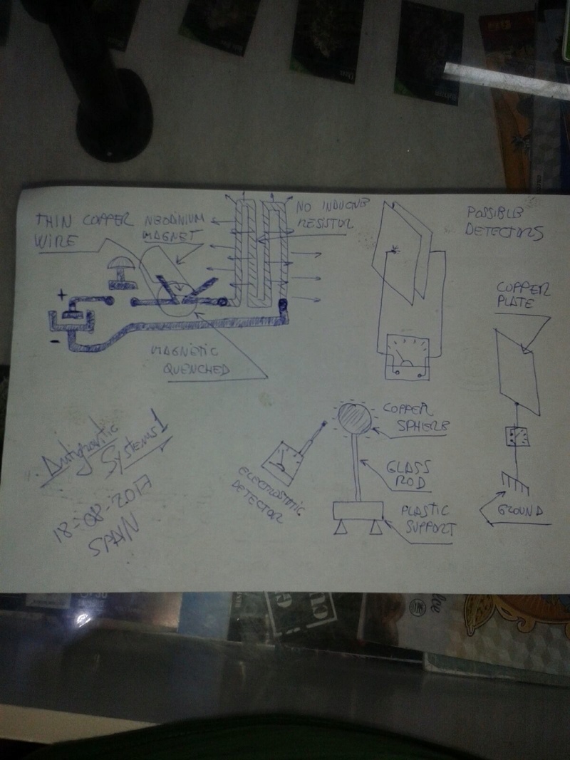
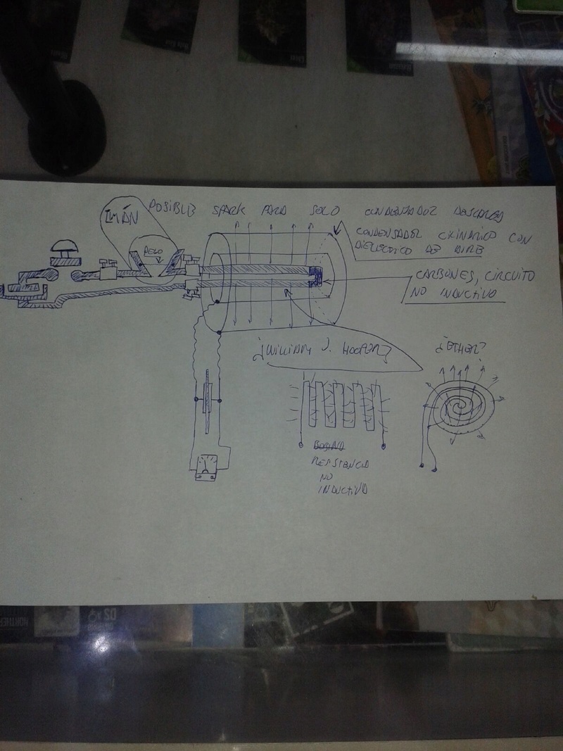
In 1957, a Russian immigrant to the USA, one Alexei Poppoff, showed Edwin Gray a circuit which he said he had been shown by Nikola Tesla. Tesla in his Philadelphia and St Louis lecture in 1893 showed how loads can be powered when a high voltage source is pulsed by magnetically-quenched sparks – this creates DC pulses of very short duration.
Edwin Gray joined up with his next-door neighbor Marvin Cole, who held a Masters degree in Mechanical Engineering and who, unlike Gray, was able to understand the circuitry.
Peter Lindemann points out that Ed Gray’s power conversion tube circuit is effectively a copy of Nikola Tesla’s circuit.
The Ed Gray Power System, the power tube presented to the public by Edwin Gray, operates by generating a series of very short, very sharp pulses using a spark gap.
From 1958 to 1972, Marvin Cole, Ed’s neighbor, working alone, designed and built ever more powerful prototype engines, and it was a small one of these which was tested by Cal-Tech. In this period, Marvin also developed ever more powerful power supplies, which are the really important item in all of this.
In 1967, Ed Gray rejoins Marvin Cole and together from 1967 to 1972, they solicited venture capital and promoted the technology.
Early in 1972, for unknown reasons, Marvin Cole disappeared [was murdered?] and never saw Gray again.
from: eduhosting.org/classes/magmotors/unity1.html
and
I also found this article interesting: https://steemit.com/science/@lamare/...in-free-energyLast edited by vidbid; 07-17-2017, 05:18 AM.Leave a comment:
-
Coming disclosure of secret E. V. GREY technology
Popping coils and splitting the positive explained at the rally in light
of the new revelations.
Al Francoeur - E.V. Gray Motors - 2017
https://www.youtube.com/watch?v=6pOV4JNFOCE
-------------------------------------------------------------

Leave a comment:
-
I was reading KeelyNet recently & noticed that in this article about electrogravitics, the US patent 4095162 by Joseph Hiddink shares similarity with Gray's Tube, in the use of the plasma in a tube as a conductor & is similar to Aaron's Plasma Ignition in the use of a second power supply to quickly produce very high voltage. (A 1-terminal capacitor sphere about 2 meters in diameter could reach 100 megavolts)
Quick thought: Could this be combined with Tesla's radiant energy receiver?Last edited by Dingus; 12-16-2015, 10:46 PM. Reason: Oh Jeez, I just noticed the same patent is mentioned in a post from 2011Leave a comment:
-
Either method might be fine for near-continuous plasma, which I'd like to use at some point for what's basically a plasma torch, but the high frequency application I was thinking of is around the 65 GHz range, using the inductor & the plasma is unused. But I'm getting way, way ahead of myself just asking about either.Originally posted by Aaron View PostLast edited by Dingus; 11-03-2015, 02:00 AM.Leave a comment:
-
gray tube
A 555 circuit switching an SCR can do it. That plasma is pulsing off and on, but for the most part, it does exist almost constantly since the turn off time is maybe not enough for it to fully decay.Originally posted by Dingus View Post
[VIDEO]https://youtu.be/8H5CuvFlU2M?t=23s[/VIDEO]
There are advantages to my plasma method but a simpler way is to simply put a cap across the gap with the diode and its own power supply. You can then use a normal ignition discharge to trigger it.Leave a comment:
-
If he did manage to have to coils run cooler it probalby just had something to do with the magnetocaloric effect or something like that, probably not worth it for low-power application.Originally posted by Aaron View Post
Yeah, I don't think it's worth it to try with anything other than a conductor, especially considering the materials that are available these days.Originally posted by Aaron View Post
Way ahead of you on that one, I like to assume anything I make myself might explode.Originally posted by Aaron View Post
Apparent continuous is good enough for what I had in mind, but testing the circuit in a simple simulator, it seems like the plasma ignition circuit is best for lower frequencies, so if there's no benefit to using the circuit at really high frequencies, then I'll just use a xenon circuit or something instead, it'll be worth testing either way. I wouldn't even know how make a switch that works rapidly enough to be apparently continuous. How would you do it?Originally posted by Aaron View Post
I actually saw that video before I started posting in this thread, I was going to with that old circuit because it seemed less complicated & with the circuit simulator I've been using, I can't seem to get the new circuit to work, while the old one shows a very obvious voltage spike at the moment the switch is flipped. I didn't even realize the difference in time stamps until just now.Originally posted by Aaron View PostLast edited by Dingus; 10-30-2015, 10:39 PM.Leave a comment:
-
gray tube
I didn't check the coils for temp that I recall, but I'm sure they warmed up - some good current pulses in them.Originally posted by Dingus View Post
The plastic was probably something conductive. You can influence any material with magnetic fields if strong enough, even plain plastic, but I don't believe it was that kind of power.
If you do experiments with any kind of glass bulbs, etc... make sure they're shielded in something safe because you could explode them easily.
This plasma ignition circuit can do apparent continuous arc with fast enough frequency, but if you want true continuous, you might need something like a xenon circuit or something. Wouldn't be the same thing, but just wanted to mention it.
That diagram you mention was very early when my HV source actually went to the grids first and charged the cap behind the inductor up. When that cap got high enough to jump the gap to ground through inductor to grids to that common ground, it caused the plasma. Would have to elaborate on that later, but that was when I was trying to do it with the cap behind the inductor and made the plasma by "accident".
Anyway, this is the real analogy between the Gray Tube patent and the plasma ignition:
[VIDEO]https://www.youtube.com/watch?v=lp-KOgU9n78[/VIDEO]Leave a comment:

Leave a comment: