Dielectrics in the E.V.Gray EMA4 Free Energy Engine
Dear Arker,
There are two main kinds of dielectrics that appear to be used in the EMA4 Free Energy Engine.
1. The 0.250" (5mm) Teflon engine case liner which provides electrical isolation between the conductive sturctural case and the internal engine components.
2. The Delrin (Trade name for this plastic made by DuPont) or Acetial which is the blocks that are installed between the electromagnetic pairs. I propose that this is the surface where the non-classical stretched arc process takes place.
Nylon and PVC are probably used elsewhere in the engines construction.
So far this is just an interesting theory on my part. The only supporting evidence comes from the work of Ken Shoulders who claims to be producing "Charge Clusters" by passing an arc over a dielectric between fixed electrodes. He has studied this process in excess of 20 years and offers a number of documents on his web site. It appears that his approach doesn't produce these particles in large numbers. If my theory is workable it must produce at leat 1000X more of these anomalous particles to begin to observe the phenomenon that has been reported.
My proposals on how this might have been done is just the result of examining the history and photos that are avaliable.
Keep in mind I could be way off on this, so don't spend a lot of money building equipment until we have more to go on.
Mark McKay
-
Dear Spokane1,
....................................
To my point VIII, I saw meanwhile your drawing : "Arc Stretch Illustration.pdf" (page 19 of the forum) that contains the answer. I guess in your experiments you connect your EMA4 like "Arc Stretch Illustration.pdf".
As for my point IX it is based on a mistake (I'm french and it's not easy for me to understand technical english) : I thought you were talking about a dielectric bonded to the poles of the cores ... Meantime, in reading your posts of previous years on this forum, I realized that the insulating material between the cores is not between their poles but between their sides.
I thought previously that these teflon blocks were vulgar wedges (for it is certain that the cores undergo significant mechanical stress). But now I understand you consider these wedges as attractors of electrostatic charges. The EMA4 would be a kind of testastika.
A priori I thought that the bow licking the teflon prohibits the storage of electrons, but I am ignoramus to 100% in electrostatic machines.
So here I'll make a break during few weeks to study the intricacies of electrostatics.
All the best.
ArkerLeave a comment:
-
Eric Dollard's Work
Dear lamare,Originally posted by lamare View Post
Thank you for pointing out the most interesting early work done by Mr. Dollard. I believe I have just about every thing he published. I must agree he did some most outstanding work way back then (early 90's).
The problem I have with Mr. Dollard is that his work never seemed to reach a conclusion. OK, all those points he was making about the construction of a Tesla Transmitter are about 20 years old. What happened? Did it work, not workout or did something better come up? I have no doubt he was on the right track or at least in the Ball Park. But, reading Eric's work is like starting an interesting SiFi novel and discovering the rest of the book is missing after about chapter 3.
Now when you get to his math I'm almost completly lost. I struggled with third year calculus and his stuff is way beyond that. I supose you have to be able to master graduate level physics math to begin to understand his three and four dimnsional partial differential equations.
Mr. Dollard and Peter Lindemann did a wonderful video about Longinitudinal Electricity where they even demonstrated the charging of capacitors from a single ended electode. What happened to that work? That experiment in itself could have been the foundation of a whole new science. Us observers are unable to reproduce what they did since there was not enough information disclosed about the performance and specifications of the Tesla Coil power supply and the Thyratrons used (with no filiment power).
If Eric's approach had anything to do with the E.V. Gray technology I would have thought that he would have been able to advance it to a marketable technology by now or at least write a few more articles on the subject. But I don't know what his situation is or his level of self funding. Rummor has it that he has been victomized by the MIB at times.
I know he is still around and on occasion posts his thoughts on the Internet on certain select subjects. But, the few of these short papers that he has written (and that I have been able to read) are beyond my feeble concepts of classical EM field theory. (Which I never did understand very well)
I do keep in mind what I can recall of his work as I extract what I can from the E.V.Gray history.
Thanks again for pointing out this reference material. I agree that his descriptions are very close to what we are exploring and his material should be close at hand as we dig deeper into this subject.
Mark McKayLeave a comment:
-
@geotron
If I understand correctly, you've been blowing out your driving FETs? I've found huge problems when switching FETs with inductive loads quickly. The back EMF spike likes to blow out the FET gate, even with a diode. I've been using SCRs in my high amperage switches, and while they are a pain, I have been able to switch 1000 uF caps charged to 340 volts at rates of 20 Hz with a large inductive load. The FETs just aren't as robust. I've been starting to play with using a plasma arc for switching, but that presents its own set of problems.Leave a comment:
-
Leave a comment:
-
I think it would be interesting to place a spring coil made of graphene in the center. Pretty sure it could withstand HV electric charges(no matter where they would appear, or plasma discharges as well considering the "toughness" of the material. Good explanation though and good luck.Originally posted by Aaron View PostLeave a comment:
-
Hi Mark,Originally posted by Spokane1 View Post
Eric Dollard wrote some very interesting details in a.o. his "condensed intro to Tesla Coils":

In his writings Tesla indicates some seemingly impossible phenomena surround the emanations from the spherical terminal capacity, and I have determined these to be true by experiment. One is that the power gradient (poynting vector) is in the same axis as the dielectric flux gradient. The other is the slow formation of a conductive area surrounding the sphere that is not ionic in nature (in other words is not a spark or glow discharge).
Contrary to popular relief, the Tesla transformer is not a steady state device but is a magnifier of transient phenomena. Also it does not behave like a L. C. network nor a transmission line, but more like a unique type of wave guide. If all parts of the system are designed properly the EMF and hence dielectric flux jumps from zero to an enormous value almost instantaneously, thereby producing an almost inconceivable displacement current into space. The transformer is then basically a device for rapidly discharging the capacitor bank nearly instantly into free space, producing an enormous dielectric shock wave similar to a sonic boom.
Because the dissipation of the transformer is for all practical purposes negligible, the energy keeps increasing at a linear rate per cycle of oscillation, thereby accumulating a gigantic quantity of electrical energy. (A form of laser action may be possible.)
It seems like a thyratron, which is gas-filled, may be such a "plasma device", as Eric also writes:The formation of the energy impulse involves the discharge of a capacitor with the highest practical stored energy into an impedance (inductive) of the lowest practical value, and the discharge path is coupled to an energy supply through a negative resistance device. This negative resistance is classically a spark discharge, but a superior plasma device needs to be developed to enhance efficiency. Under optimal conditions the exponent of oscillation amplitude will be positive over a sustained period of time.
The net result of this system is the production of an extreme impulse of M.M.F.. An alternate method is the discharge of an inductor of the highest practical stored energy into a circuit of the lowerst practical admittance, thereby producing an enormous impulse of E.M.F.
It may be worthwhile to check this out, as well as Eric's other theories:Due to the immense difficulties surrounding the spark device, a simple method and one of much greater control is shunt feed of the primary network by an A.M. radio transmitter of special design such as the unit at building number one. Due to the high impedance offered by the primary resonator the impedance effective of the tubes must be high and therefore must operate at high anode voltages. The electron emission however, must also be high, necessitates large cathodes and temperatures. High anode and large electron emission are usually of inverse relation in available vacuum tubes. Special pulse modulator vacuum tubes must be used. Hydrogen thyratrons might operate satisfactorily at low frequencies where the 1 microsecond deionization time will not hinder commutation. The most effective device for shunt feed may be the multipactor tube due to its strong negative resistance effects, but it is not clear if it will operate below 1000KC with much efficiency.
By the utilization of the aforementioned devices a much improved field is developed at the transformer output with regard to stability. This I have found desirable for the production of stable plasma formations.
However, I have not noticed the "jamming together of electrons" unless the spark method is used as the rate of rise of EMF is much greater by the spark method. Perhaps the multipactor will operate comparatively but strong impulses do not seem possible with shunt methods.
For stability of certain plasma effects AFC may be required. (See Fig. 5) The image coil system exhibits strong discriminator effects and thereby facilitates the formation of an error signal to the V.C.O.
As to physical construction the primary should be sheet copper of great conductor width and large loop area. Large surface is required as the skin effect is total with impulses. Large width also minimizes inductance allowing for larger capacitors and more rapid discharge and hence high impulse strength. In opposition to this required inductive reduction is the need for a large area due to the flashover and coupling requirements. Hence a balance has to be established between the need for minimum inductance for rapid discharge and for a large magnetic field, resulting in large inductance.
Directory contents of /pdf/Eric_Dollard_Document_Collection/
IMHO, he gives you all the fundamental theories you need.Leave a comment:
-
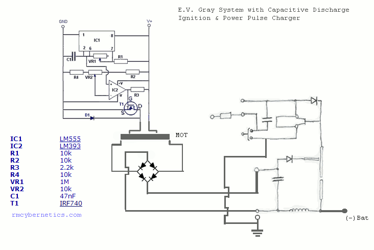
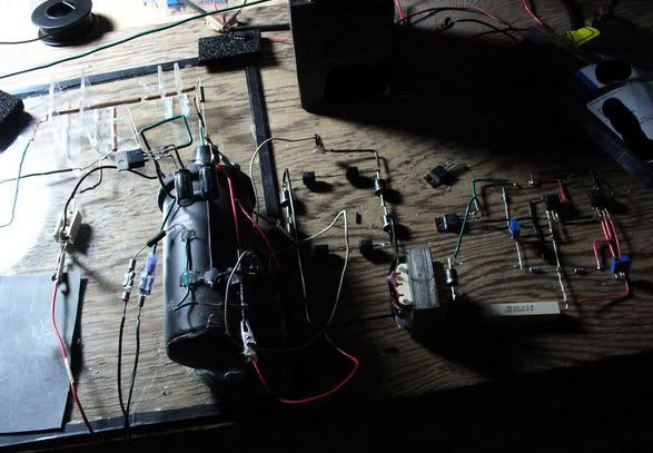
 Guest repliedThe following is how I've set it up... the CDI is charged up with a secondOriginally posted by geotron View Post
power pulse charger circuit separate from the one shown. At this point I'm
thinking that perhaps the HV plasma burst from the ignition coil may be what
is causing the power pulse circuitry to blow out due to their common
connection to Ground.
Would adding a few blocking diodes (~3kv) in series to the power pulser
ground be a good idea?
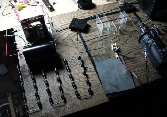
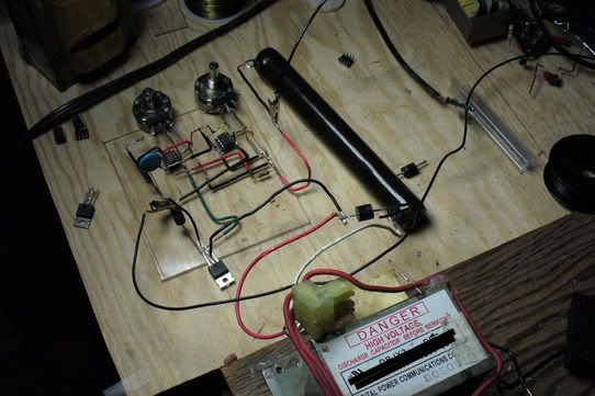
Suggestions are more than welcome; I've currently got two working mosfet
transistors left, so this will be just enough for experimenting. The photos
show how I modified it from the diagram as it is shown to have a diode across
the primary of the transformers as an experiment, alright for the CDI but
not for the LV as it has a substantial quenching effect on the output.
 Last edited by Guest; 06-07-2011, 03:13 PM.
Leave a comment:
-
More EMA0 Information
Dear Arker,Originally posted by Arker View Post
Here is some more comments on your questions concerning the EMA0 model.
Questions from section VIII
-The non-classical arc is the one that I believe generates the anomalous particles. However it appears that other fixed arcs were employed for timing and trigger purposes. I propose that the non-classical arc took place between the core faces of the opposing Minor electromagnets, but I could be wrong. Richard Hackenberger thought the non-classical reaction took place in the front section of the commutator between the switching discs and the fixed contacts. Both locations produce a stretched arc.
Questions from section IX
-The construction of a variable capacitor within the design of the engine is vital to my theory of electrostatic energy harvest. This is how energy can be pumped from highly charged dielectric surfaces back to the storage capacitors. This is assumed to be a classical process. However the creation of the static charge is a result of a breakdown of the anomalous particles.
-No, the potential difference is not allowed to exceed the stored charge on the capacitors. This is achieved by means of diode and the lead acid battery. Were this circuit not in place the potential would easily exceed the breakdown potential of the air.
-to my knowledge there was no Teflon coating on the face of the cores. At least that is what the situation appears too been in the available photographs. Now the inside of the engine case was lined with a 0.250" Teflon layer. This was to isolate the electromagnetic base plates from the conductive engine case. I suspect this provided a fixed capacitance that worked with the electrostatic harvest method. Notice the huge conductor that connects to the engine case. There were some provisions for some pretty hefty currents to slosh between the batteries and the engine case.
-The size of the storage capacitors is around 5-12 uF (microfarad). This was observed in the Bedini Field notes. I believe the EMA4 use the smaller capacitor size. Yes you are correct in that the stored energy can be determined by knowing the size of the capacitor and the applied potential. But this tells us nothing about the nature of the anomalous particles generated.
- I shall send you a paper on this subject (Chapter 6) and we can discuss this interesting matter further.
Mark McKayLeave a comment:
-
Un-noticed topology Details of the Tesla Exploding Wire Experiment
Dear antigraviticsystems,Originally posted by antigraviticsystems1 View Post
Allow me to add additional technical information to this important Tesla experiment that was explored in early 1891.
-The power supply was composed of a SMALL capacitor and a highvoltage constant current generator. This has a huge impact upon the energy profile that is presented to the arc plasma.
- Dr. Tesla explored the phenomena that traveled at 90 degrees to the conductor, but then went on to examine what anomalous particles continued down the length of the conductor. His later work focused on these particles before he came full circule to advance and improve upon the 90 degree process in 1903.
- The system(s) devised to turn off the current were manditory because of the current source supply.
-The magnetic disrupter only disclosed part of the complete system. True the applied magnetic field did eventually quench high current arcs, but what it was doing in the microseconds before the quench is far more important. Consider the dielectric that Dr. Tesla used to protect the pole faces of those magnets. As the arc is twisted due to the applied magnetic field the plasma is physically drug across a dielectric sheet (normaly Mica). The concept of a stretched arc across a dielectric surface is explored by Dr. Tesla in several manifestations from 1891 to 1907. No less than 11 patents have this common theme.
- Dr. Tesla quickly abandoned magnetic quenching very early in the decade becasue of the energy requirements and the persistant instability of plasmas in magnetic fields. by 1985 he had patened several intrupter designs. It is assumed that the most advanced designs used mercury jets.
- The abrupt quench has more to do with another un-observed process than anything presented so far. The quick break allows for the generation of an RF burst across the electrods of the gap and thus saturate the cooling arc plasma with a specific RF frequency. This action seperates Dr. Tesla's work from the operation of commercial high-voltage switching. This process step is critical in the production of the anomalous particles.
- True electrons are lazy and consume energy to move from one place to another, but i doubtr that is what Dr. Tesla was striving for or working with. He generated a whole new class of energetic particles which I call "Tesla Radiant Energy Particles" (TREP's). This is where the action is at. Classical electrons are a pain, but under the influance of a postive ion matrix in a properly designed arc the might become a "Charge Cluster" with unique properties.
- These TREP's (or etheric energy) have a huge magnetic moment, as if the electron spins are all locked into the same phase. Thus they act as super conductor particles and travel through metallic crystals (ie wire) as if it were a super conductor. I would guess that any OU properties to be utilized are a function of all these spins interacting with the zero-point vacuum energy (or what ever it will be called)
Keep up the good work and the detailed research experiments. Your description above is fundamental to the birth of a new physics. These same ideas seem closely associated with the E.V. Gray technology.
Mark McKayLeave a comment:
-
Originally posted by nat1971a View Post
I found an interesting intro into thyratrons:
The process of switching in a hydrogen thyratron can be broken down into four phases. These are voltage hold-off, commutation, conduction and recovery.
Interestingly, there's a part about how thyratrons compare to spark gaps:
Some more on thyratrons here:
Gas discharge tubes : THYRISTORS
It's behavior appears to be very similar to a thyristor.....In essence, thyratron tubes were controlled versions of neon lamps built specifically for switching current to a load. The dot inside the circle of the schematic symbol indicates a gas fill, as opposed to the hard vacuum normally seen in other electron tube designs. In the circuit shown above in Figure above. the thyratron tube allows current through the load in one direction (note the polarity across the load resistor) when triggered by the small DC control voltage connected between grid and cathode. Note that the load's power source is AC, which provides a clue about how the thyratron turns off after its been triggered on: since AC voltage periodically passes through a condition of 0 volts between half-cycles, the current through an AC-powered load must also periodically halt. This brief pause of current between half-cycles gives the tube's gas time to cool, letting it return to its normal "off" state. Conduction may resume only if enough voltage is applied by the AC power source (some other time in the wave's cycle) and if the DC control voltage allows it.Leave a comment:
-
Guest repliedWell guys, in my previous experiments with the CDI ignition and variac
method of charging up the LV side cap bank, apparently the limiting factors
in producing negative results on charging the battery were -
1) The CDI ground from the (-) ignition coil was not on a spark gap to
the cathode of the battery. The Ground wire on the 3rd point ought to
have been on a gap with the CDI ground on the other side away from the battery.
Not doing so was bumping the current draw.
2) The various operating parameters of the variac and inverter were drawing
extra current to stay operational while also powering the coil-driver circuitry.
Aaron, I've rebuilt your system once again, this time completely by the use
of the pulse-width modulated 555 & 393 mosfet circuit designed by the RM Cybernetics
team. The outlay of the entire thing is identical besides the use of a variac and
inverter.
The results I've obtained in this manner are quite promising.
Attached is the matching diagram, and might I convey that while it was working there
was an unmistakable charging effect on the battery.
Due to what I believe is a fault in the circuitry for driving transformers the
system did not last more than 5min before frying the mosfets without overheating
them, while also disabling a number of timer & pulse-width chips. I've hence
rewired a diode to be positioned across the MOT primary to subside any spikes
that might be causing the problem and it has unfortunately worked to reduce the
output to a minimal value.
How indeed I might progress to rebuild it to stay running is almost
Leave a comment:
-
@Pranav
Looks good Pranav, congratulations! I saw the vids when you posted
them - looks very stable.
Are you going to do tests with the coil punching a magnet?Leave a comment:


Leave a comment: