Announcement

Collapse
No announcement yet.

Gray Tube Replication

Collapse
X
 
  • Filter
  • Time
  • Show
Clear All
new posts

  • Guest
    Guest replied
    Colliding Positive Potentials

    The phrase 'splitting the positive' could possibly be an enigmatic
    interpretation of the process by which two potentials are collided
    together with the use of electronic components.

    The energies of each positive potential are in such a state as to allow
    direct contact with realm of quantum mechanics through the use of
    techniques pioneered by Edwin Gray and his predecessors.

    In the patented figure there are a number of coils connected in a way
    such that the potentials will find a balance and the motor will operate
    efficiently.
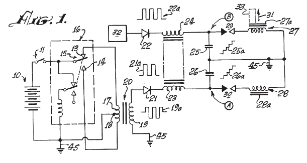

    [ click for patent ]

    In the patent given to E.Gray on his power supply for inductive loads, a basis
    is presented - using the properties of a diode mechanism to enable the pressurization
    and fracturing of a low voltage potential through an opposing voltage of greater
    magnitude.

    Thus in going with the way it is shown above, efficiently driving each of the
    motor coils with a secondary capacitive element opposed to the primary one
    would inherit the ability to cause compression of the energy sitting within
    the coil before it is released in the form of mechanical energy, providing
    a momentary thrust of output power greater than there would be otherwise, or
    so the matter would seem.
    Last edited by Guest; 08-05-2011, 12:48 PM.

    Leave a comment:


  • Guest
    Guest replied
    (...........will update........)
    Last edited by Guest; 08-05-2011, 11:25 AM.

    Leave a comment:


  • Guest
    Guest replied
    Originally posted by pranav2010 View Post
    hi aaron

    this is my circuit

    have wonderful day
    pranav,

    What an amazing schematic... how you've connected the primary
    ignition coil to the output of the charging cap bank.

    Its similarity to Ed Gray's patent seems as though the HV cap bank 16
    from Fig 1 is what you have now added above the ignition coil charger.

    You have the output of pickup coil
    hooked onto the Anode, why not place a battery bank in series with
    the low-voltage side capacitance, providing the anode with a burst
    from the output of the motor coil

    With the plasma serving to cause
    the reaction perhaps replace that whole side with a battery
    Attached Files

    Leave a comment:


  • nat1971a
    replied
    Guys

    I just stumbled onto the exact model of thyratron that gray was using.

    It turns out he was using a mercury ignitron GL-7171


    So I will have to start learning how to use these now

    Source is the YouTube video called ev gray motor found

    ‪EV Gray Motor Found!‬‏ - YouTube
    Last edited by nat1971a; 07-15-2011, 12:57 AM. Reason: .

    Leave a comment:


  • antigraviticsystems1
    replied
    Originally posted by antigraviticsystems1 View Post


    Uploaded with ImageShack.us

    Leave a comment:


  • antigraviticsystems1
    replied


    Uploaded with ImageShack.us

    Leave a comment:


  • nat1971a
    replied
    YouTube - ‪Update 41 - Edwin Gray Tesla / disruptive discharge hybrid circuit - shorting CAP‬‏

    Here's a brief video of the cap shorting..voltage isnt as high this time around for some reason

    Leave a comment:


  • nat1971a
    replied
    Looks like i spoke to soon. Someone on the forum mentioned shorting out the capacitor. So i tested that today. Well that gives me anywhere between 50 and 350 volts too. My setup is almost exactly like grays now except i don't have a connection between the negative of the batterys and the negative of the HV capacitor. And no battery powering the filament of the thyratron

    What does appear to make the difference is Tesla's zinc box that i am using. I moved one of the 10 turn coils to another part of the circuit as a test and i got absolutely nothing.

    So what appears to work is having a 10 turn coil on the positive of the HV cap and another oppositely wound 10 turn coil on the LV side (before the resistor/ thyratron). I borrowed that idea from grays earlier patent.

    Leave a comment:


  • nat1971a
    replied
    Remove the short from the circuit diagram. It isnt in my circuit

    I am also using a neon to trigger capacitor 38 (grays circuit) as per Tesla's radiant energy patent.

    If one compares Tesla's radiant energy patent, the hammand patent and grays patent. I think we can come up with a working system using grays circuit as a template. All three patents are missing key components.
    Last edited by nat1971a; 06-30-2011, 01:24 AM.

    Leave a comment:


  • StweenyA
    replied
    cap still shorted.

    Hey, did you watch Peter Lindermann's vid? He pointed out that part 42 is shorting the cap to ground, in which case it wouldn't be able to charge at all. It seems you have removed the one line at the bottom. But I don't think that's going to solve the problem, the + of the cap is still connected directly to ground via part 42. Or am I missing something?

    Leave a comment:


  • nat1971a
    replied
    A picture is worth a thousand words...AC feeds back from the primary to the secondary battery. It then proceeds to conduct through the coupling capacitor 38 on it way to the grid of the thyratron. This setup mirrors the hammand patent as close as i can.
    Last edited by nat1971a; 02-10-2012, 08:42 PM.

    Leave a comment:


  • Guest
    Guest replied
    The modified pc fans trigger coil produces roughly about 10-15 VAC.
    I have connected that to a 12v cap connected to the grid of the thyratron
    at the moment.
    Have you grounded the cathode of this capacitor, which you have since replaced
    with a different one to obtain this new voltage?

    The diagram of your system is then a battery-interrupted charger on the filament
    to act as a cathode, high-voltage AC capacitor [ 38(Gray) 3(Hammond) ] to condense
    energy as in Tesla's patent 685957 Apparatus for Utilization of Radiant Energy
    from the grid to pass through the filament power supply interruptor and on to
    once again be interrupted through onto the plate?

    Have you connected your condenser capacitor in parallel or series with the coil?

    The difference in operation of these two methods does not immediately seem clear.

    Leave a comment:


  • nat1971a
    replied
    Well i think i have reverse engineered a key portion of grays circuit with the help of the hammand/Tesla patent.

    I am now seeing the beginnings of what looks like my battery's are charging. I am also seeing a steady 90-107 volts in the charging cap 38. However i am killing the thyratron. So more work required to make this stable

    The inspiration came to me when i started to compare obvious components in the two patents.

    Capacitor 38 in grays circuit is a coupling capacitor in that it conducts AC

    Leave a comment:


  • nat1971a
    replied
    The modified pc fans trigger coil produces roughly about 10-15 VAC. I have connected that to a 12v cap connected to the grid of the thyratron at the moment.

    Leave a comment:


  • Guest
    Guest replied
    How are you switching the voltage into the thyratron? With the info from
    Hammond compared with that of Magratten and Bedini, the object seems to
    be slightly different. Whereas in Hammonds vacuum tube the radio frequency
    obtained from an antenna is pulsed from a secondary pickup coil in tune
    with the pulse heating the filament cathode and other parameters for the
    purpose of obtaining contact with background energy, the radiant discharge
    from pointing a high voltage signal onto a switched low voltage source
    with the blocking rectifier happens whereby the low voltage is combined with
    the high voltage in an explosive transfer of energy as in Gray's Tube.

    -----

    The pwm circuit diagram is misleading. The 1k ought to be replaced with the base
    of a small signal transistor switching 12v into a 100ohm resistor onto the gate.

    Leave a comment:

Working...
X