Well i have tested a HV cap and a LV cap on the grid of the thyratron. The difficult question is what was Tesla/Hammand using and what was gray using.
HV cap seems to give interesting results but i suspect damaging the thyratron.
So i am presently continueing to test a 12v cap on the grid of the thyratron. Apparently only between 1-20VAC is required to operate the thyratron.
Anyway i was randomly testing things yesterday. I hooked up the safety overshoot as per grays schematic and set it close to the charge receiving grids of the CSET. Well i always suspected that a negative pre charge was required on the charge receiving grids as per other information i found based on Tesla's references.
Anyway this has provided some very interesting results. Making my neons light up and caught me off guard. It was producing between 50 - 350volts so it doesnt appear to be HV. And was effecting the charging battery. I will investigate further in this direction.
The video below talks about Tesla's reference on a negative pre charge
YouTube - ‪Update 30 - Found missing info from Tesla Radiant Energy Patent‬‏
-
 Guest repliedThe way things are going with the pwm mosfet circuits I've built
into chargers for the plasma ignition and low-voltage side cap are not
so well.
With a bit of help it may begin to work for more than 3-5 minutes at a
time before causing the transistors to quit. They're php18nq10t and
I've got them with a 1KV rectifier from source to drain, while they're
rated for 100v. Perhaps 2KV would work better... as a matter of fact
I don't seem to remember having one work properly yet for more than 30sec,
at one point going back to an old irf740 of which subsequently is also
now malfunctioning.
The battery voltage jumps around when it decides to work then recovering
from 12.7~ to 12.9~ when it is shut off or breaks.
One pwm for each side, set up with a 10k + 100nF in series from the primary
transformer output to its other primary side.
The ignition coil is grounded and there appears to be full absorbtion into
Ground without any frizzing metal contacts upon discharge.
Both the HV and LV side supplies have now ceased operating... its now with
a dual 555 timer chip and is seemingly magnificent at producing accurate signals.
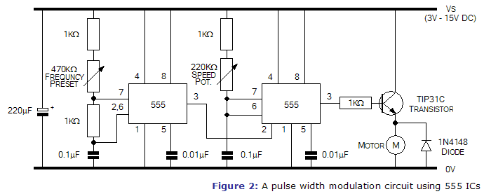
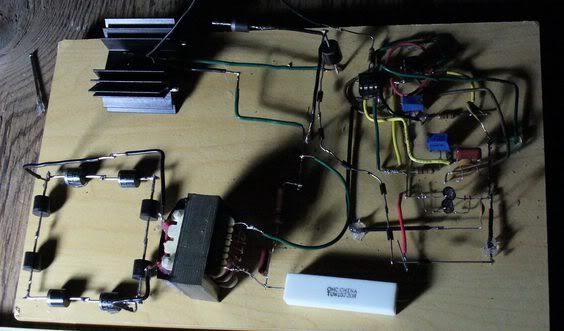
Both sides are set up as shown, only the LV side is on a MOT and has 10ohms in
place of 20 into the primary.
Leave a comment:
-
i suspect its broken. Just trying different setups to see what does what.
Strange thing happened yesterday. I tried reversing the charging cap (38 on grays circuit) so that a negative charge was sitting on the charge receiving grids instead of positive (and added some resistance in too)and when i turned the circuit on for a while and then off. It kept running (it kept discharging) for about 10 seconds while switched off...Really strange stuff happening. the thyratron was still powered on though. havent seen this beforeLeave a comment:
-
Guest repliedcustom glasswork and vacuum pressure
There appears to be some kind of an interruptor for the filament kind of built
onto the cathode of battery 5 in figure 3. Using a pulsewidth modulator on each side
and tuning it by observation may prove worthy.
Will the tube you previously mentioned that stopped after ~5sec return to a
useable state? Around part 70 Page 2 is in reference to the tube becoming unusable due
to a lack of enough heat being generated by the filament.Leave a comment:
-
I tested this circuit (hammonds/Tesla's thyratron driver circuit) on the weekend and I do get a high reading on capacitor 38 (grays circuit) when i initially turn on my circuit but then it stops after about 5 seconds. I wasn't interrupting the flux current. Didnt seem to work when i did that.
Interesting to say the least!
Not sure if you picked up in the patent. He mentions using a mercury vapour thyratron!! This should make you think about Tesla's oscillators using liquid mercuryLeave a comment:
-
Guest repliedIn Figure 3 the grid at 6 looks as though its only connection is to the condenser
3 and secondary side of the transformer. The variable current into filament 5 looks
to be looks to be accomplished by a potentiometer symbol built onto the cathode of
the battery.
At the end of part 10 on page 3 is said that it is possible to stop any brush effect
by increasing the vacuum although in order to obtain the most sensitive
conditions of this device there is a critical pressure balance to be obtained
at what seems likely to be a lower value. This brush effect ought to then be
something non-effectual to a properly functioning detector...
In page 4, part 15 Hammond says he interrupts both the current of the flux
and the filament circuits; it seems that he is referring to the rectified
flux circuit 24 (fig.4) by the nature of electrical reaction in the vacuum tube
between the grid, (+)collector and (-)filament providing DC by way of the grid
holding onto negative charge.
--------
John Hays Hammond
Gaseous Detector of Radiant Energy and Method of Control Thereof
1,610,371Leave a comment:
-
Hi All,
I have decided to release further information as a starting point.
Please read this patent. What is not very well known is that Tesla resided with hammond for a while.
Now comtemplate how this applies to grays circuit.
Regards,
Nat
 Last edited by nat1971a; 02-10-2012, 08:42 PM.
Leave a comment:
-
Hello everyone ,
See My video and say me why the grid of CEST (in Gray circuit) is just only
around spark gap and anode HV and LV whereas radiant pressure or
sort of ethear appears and start after HV supply ? So Why a grid just here
and not everywhere ? . . . Because It fell me absurd
= = = = VIDEO LINK = = = =
YouTube - ‪Radiant Energy Experimentation Inspired By Nikola Tesla‬‏Leave a comment:
-
Guest repliedskaght,Originally posted by skaght View Post
That's interesting... I'll definitely be running some experiments with
the SCR diode then - and there's something else that might be of some use,
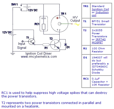
if one wishes to only use the mosfet, the RMCyber diagram for switching
ignition coils shows a .1uF & 10k pair on the collector side or rather in
our case the drain for supressing the inductive spikes from causing damage.
I've attached this below.
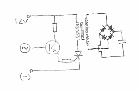
In the case of using the SCR then, I'm thinking it ought to look very
similar to the following, with 1K resistors around a small signal transistor.
Leave a comment:
-
I was able to do some more tinkering on the weekend using a used large form factor 15KV Gas filled thyratron.
Circuit modifications.
1. Connected wire from negative terminal of HV cap (item 16 in grays patent) to the negative of the charge receiving battery (18).
2. Setup the entire Tesla thyratron driver circuit as per my information.
Observations.
1. Scary HV evident in entire circuit. You could hear it. Significant increase in voltage through entire circuit. Didnt bother to measure it. Would probably ruin my equipment
2. Intermittant voltage readings on charging Capacitor (38) in the range of 1-10volts while firing relay (item 26 in grays patent)
3. No visual evidence that the thyratron was triggering
4. Evidence of slight charging on heater battery (battery that powers the filament of the thyratron)
My conclusions
1. Further evidence that a diode on the LV side is detrimental to the performance of my circuit (noticed in previous experiments with a diode instead of thyratron) whilst in conjunction with circuit modification 1 as listed above
2. More testing required with other thyratronsLast edited by nat1971a; 06-08-2011, 04:48 AM.Leave a comment:
-
The etheric fluid Question
Dear antigraviticssystems,Originally posted by antigraviticsystems1 View Post
I agree with you in that radiant energy is not composed of classical electrons (I propose they are phase locked clusters of classical electrons - but this has yet to be demonstrated)
Do you know of an experiment that can demonstrate the uncoupling of the classical electrons from the etheric fluid? Once this decoupling is acheived what instrumentation might be used to determine the nature of the etheric fluid and establish its individuality.
You say (possibily from your own experiments) that in this process the etheric fluid is only visiable for a short time. What wave lengths of light do you think are emitted? Do you think what is being observed is classical photons? Any idea as to how classical photons can be generated in the absence of classical electrons? Would you congecture that the observed light might be polorized or coherent?
When you say these effects are only visable for a short time. Are we talking about microseconds or nanoseconds? Any idea as to the degree of intensity involved in lumans or candela. Does one need a photomultiplier to observe this process?
You say you are opening a circuit. Could you describe in greater technical detail how this is acheived? Are you using a mechanical method, solid state method, thermonic emission approach (vacuum tube), or some other kind of control means. Again what kind of switching times are needed?
Mark McKayLeave a comment:
-
As to physical construction the primary should be sheet copper of great conductor width and large loop area. Large surface is required as the skin effect is total with impulses. Large width also minimizes inductance allowing for larger capacitors and more rapid discharge and hence high impulse strength. In opposition to this required inductive reduction is the need for a large area due to the flashover and coupling requirements. Hence a balance has to be established between the need for minimum inductance for rapid discharge and for a large magnetic field, resulting in large inductance.
Lamare...what would you think of replacing the primary copper coil with a graphene coil. Graphene is a semi-conductor with properties that nearly resemble superconductors. It is harder than diamonds even though it is only one atom thick yet is bendable so it could be fashined into a coil. I'm sure it could withstand HV discharges as well as the damaging effects of plasma discharges. I'm sure this would help with more rapid discharges considering the lagging effect of the electrons. Or another alternative if you are insistent on sticking with copper could be (Tl4Ba)Ba2MgCu8O13+ this new superconductor operates at 17 degrees F. or 8 degrees C. check it out and tell me what you think...
Record Superconductivity Approaches 265KLeave a comment:

Leave a comment: