-
yes,I believe the essence is that triod is a source of electrons and based on thyratron used quite a big current is generated. In summary here is adjustable ground connection via spark gap to balun antenna.We are closer. Element 42 could be wrongly drawn or just a switching device which shorts capacitor and then collect "something" to recharge capacitor from running coils (bemf or electrostatic charge running along wires) - kind of electrostatic relay normally shorting capacitor but when electrostatic charge occur in wire connected to running coils then connection is established to recharge capacitor. -
Circumference of coils related to wavelength?
I just realized that the circumference of the load coils may be an important parameter too:
For calculation of these circular resonances, we have the Schumann formula:Originally posted by lamare View Post
Of course, we would have to calculate with the correct wave propagation speed, which would be pi/2 times c....Originally posted by lamare View Post
Update:
Spark gap oscillators have been used at frequencies up to 60 GHz, already in the late 1800's:
J.C. Bose: 60 GHz in the 1890s
Figure 3 (a) shows Bose's diagram of one of his radiators, used for generating 5-mm radiation. Oscillation is produced by sparking between 2 hollow hemispheres and the interposed sphere.
Energy Citations Database (ECD) - - Document #6386956
Spark switched L-C Oscillator (LCO) transmitters have operated in the Low, Medium, and High Frequency Bands (10's of kHz to 10's of MHz) throughout the history of radio. In the 1970's they were pushed into the vhf Band by Moran, et al. By applying ultra-fast gas switching techniques and by overcoming spark gap losses the authors have operated LCO transmitters in the uhf (300 MHz to 3 GHz) region. Repetition rates >1 kHz with peak voltages >100 kV have been achieved.
Technical Tidbit - June 2001, A Static Field Powered EMI Source
The characteristics of a spark are determined mostly by the arc length. A number of factors influence arc length including voltage, speed of approach for moving pieces, and atmospheric conditions. The gap in Figure 2 is a fraction of a millimeter. For such a small gap, the risetime of the current when a spark forms is very fast and the current waveform is repeatable. Low voltage ESD events, a few hundred volts or less, can have risetimes in the tens of picoseconds range. A high voltage spark with a relatively long arc length results in a slower risetime of the current and the current waveform may vary between successive sparks. A 10 kV discharge may have risetimes of tens of nanoseconds. The resultant di/dt for a small, low voltage, arc is higher than for high voltage events and in many instances is more likely to result in a system upset.
So, it appears high frequencies can definately be obtained using spark gap oscillators...Last edited by lamare; 01-10-2012, 12:00 PM.Leave a comment:
-
Why a triode and no diode in the patent?
I have just been trough some documents and stuff, a.o. some of Mark's documents he sent me to publish at my site:
Directory contents of /pdf/Reference_Material/McKay_Gray_Material/
At some point, I took a look at the triode, which has been used by Gray in his stuff and has somehow been replaced by a diode by later experimenters, under the assumption that this was just a simple diode. However, there are other diodes in Gray's circuit so Gray's engineers clearly were aware of the existence of the semiconductor diode. So, how come they used an old-fashioned triode and not a much simpler semiconductor diode?
There is an interesting detail about the working of a triode:
The triode : ELECTRON TUBES
Essential for the operation of a triode tube is that the cathode needs to be heated in order to emit electrons that become a current once an electric field is applied. So, with such a tube you only need an electric field in order to get a current, without the need to feed the thing an electron-based current yourself!Another problem with triode behavior is that of stray capacitance. Remember that any time we have two conductive surfaces separated by an insulating medium, a capacitor will be formed. Any voltage between those two conductive surfaces will generate an electric field within that insulating region, potentially storing energy and introducing reactance into a circuit. Such is the case with the triode, most problematically between the grid and the plate. It is as if there were tiny capacitors connected between the pairs of elements in the tube:

Now, this stray capacitance is quite small, and the reactive impedances usually high. Usually, that is, unless radio frequencies are being dealt with. As we saw with De Forest's Audion tube, radio was probably the prime application for this new technology, so these "tiny" capacitances became more than just a potential problem. Another refinement in tube technology was necessary to overcome the limitations of the triode.
In other words: the triode is voltage driven and not current driven.
Typical capacitances are very low:
Miller Capacitance
Besides that, the cathode consists of a considerable surface of metal (compared to a silicon diode) which reflects HF waves up to a certain degree.The majority of the input capacitance of a triode stage is made up of the combination of the grid-to-cathode capacitance, plus the Miller capacitance formed by the grid-to-plate capacitance multiplied by the stage gain plus one. The formula for determining the total input capacitance of a triode stage is as follows:
Cin = Cgk + Cgp*(A+1)
where: Cin = input capacitance
Cgk = grid-to-cathode capacitance, composed of the internal tube capacitance plus the stray capacitance
Cgp = grid-to-plate capacitance, composed of the internal tube capacitance plus the stray capacitance
A = stage gain
The typical interelement capacitances are very small, but, as can be seen from the above equation, the grid-to-plate capacitance is multiplied by the gain of the tube stage plus one, so if the gain is large, the capacitance can very easily become significant, resulting in audible rolloff in frequency response.
Example
For example, a typical 12AX7 stage has the following capacitances and gain:
Cgk = 1.6pF + 0.7pF stray = 2.3pF
Cgp = 1.7pF + 0.7pF stray = 2.4pF
A = 61
Therefore, the total input capacitance would be:
Cin = 2.3pF + (61+1)* 2.4pF = 151.1pF
Now if we assume that somehow longitudinal dielectric waves were used in the operation of Gray's stuff, we would have a wave that is free of any electron-based current and magnetic fields and propagates at a speed of pi/2 times the speed of a transverse wave. In order for such a wave to be created by the rods across the spark gap, you would need it to resonate.
An interesting detail with regards to a resonating conductor is that at resonance, you either have a longitudinal dielectric wave OR a transverse wave. For a certain length of wire, for example, the 1/2 lambda longitudinal resonance frequency corresponds to 3/4 lambda transverse:
pi/2 * 1/2 = 0,785398163
multiply that by 4/3 and we get: 1,04719755
So, whenever one of the two waves is in resonance, the other one is almost completely supressed!
All right. Now if we want to get our main rod spark gap antenna into a longitudinal resonance mode, we do have to make sure the top of our "antenna" is not too heavily loaded *and* we have to make sure our spark gap is in it's negative resistance region of operation. Which means you need a DC bias current going trough it, preferably one you can adjust.
Now with a semiconductor diode, you have no way of controlling the bias trough your spark gap. But, with a triode, you have a grid...
A grid that is there for the purpose of *controlling* the amount of current going trough the cathode. You know, the connection to your spark gap. In other words: you can bias your spark gap with the triode grid and thus make sure the spark gap operates in it's negative resistance mode.
The mode needed in order for it to amplify/sustain an oscillation in a series LC circuit, whereby your spark-gap is in series with the L and one or more C's.
For the frequency of your LC circuit, the capacitance of the cathode appears to be the smallest one, so that one would determine your oscillation frequency, together with the L of the rod and the other capacitances in there, like the one between the rod and the grids of the CSET.
So, high voltage capacitor 16 discharges trough the spark gap to establish the arc and put the spark gap into its negative resistance region of operation, whereby the grid of the triode controls the current and therefore discharge time of capacitor 16.
Once the spark gap is into it's negative resistance mode, the rod forms a HF series resonance circuit together with the capacitance of the grid-kathode capacitance, whereby the grid is connected to a DC voltage.
Because of the bazooka/sleeve balun in the shape of the CSET grids, no HF magnetic field can be established at the resonance frequency, and therefore you get a longitudinal resonance mode in your system in a very similar way as what I do with my longitudinal antenna design....
To make a long story short:
1) you DO need a triode and NOT a diode
2) you DO need extra circuitry in order to bias the spark gap trough the grid of your triode...
Any questions?
 Last edited by lamare; 01-10-2012, 11:12 AM.
Leave a comment:
-
alternating electrostatic field
Hello Mr. McKay, a repeating of Nikola Tesla's "alternating electrostatic field" :Originally posted by Spokane1 View Post
Inventions, Researches and Writings of Nikola Tesla - Thomas Commerford Martin - Google Books
At least we know that this is an electrostatic phenomena.
WicaksonoLeave a comment:
-
AS I said it was related to cables I was using and place when experiment was done with large metal tabletop with big iron vice as a ground. Every metal around up to 2-3 meters from active device was charged but not to the point of bluish sparks coming out of it but like when you are charged by rubbing and got shock when touching grounded metal.Also stinging sensation was clearly felt.My friend who is EE was in place and was amused by the amount of energy radiation in air from this 36W input. Later I've found that my battery was depleted and I have never bring it to good shape again.End of story.Originally posted by Spokane1 View PostLeave a comment:
-
Non-repeatable Observations
Dear Boguslaw,
It's a ***** when we observe something interesting - then can't get it to happen again. Usually this takes place just as some critical component blows out. After it is replaced the circuit never works the same.
I have had this happen with a Tesla Coil that was causing every metal obgect in the shop to emit blue sparks - before the NST fried. Never could get it to do this again (1994)
Transistors a great for giving spectaluar results before they self destruct as well.
All I can say is hang in there. At least you have the circuit schematic of what cause the anomalous behavious. We don't even have that much for the Gray Technology.
Mark McKayLeave a comment:
-
Best Wishes for Moon Bounce Experiment
Dear lamare,
I offer my best professional wishes for you and your group's attempt to bounce longitudinal waves off the Moon. It is nice to see an organized group effort come together to explore new phenomena.
Mark McKayLeave a comment:
-
My thoughts : when due to EMI device was confiscated in 1977 there was the end already because device was not tuned, spark gap in element 42 generated huge amount of radio waves instead of working silently. Here is the connection with kapanadze silent spark gap. In 2005 I experimented with car coil driver wih very low frequency between 50 and 100Hz crude one. I tried to get working incandescent bulb as a plasma globe without comprehention that circuit produce too low frequency. Suddenly parameters (wire length frequency grounding to large iron vice and a few others) match and I've got stinging sensation in air very intense for this amount of power. I remember that I tried also to build Gray tube and ended with two copper tubes connected on one and by wire and insulated from each other by rubber pieces. I don't know why I wanted to test such strange experiment but I took large screew insulated on both ends and placed a metal paper clip below as a spark gap. Then I placed it like in Gray tube inside copper shield and everything inside car coil HV terminal standing up. In the end when I grounded device spark gap become silent and fluctuating while still white-yellow in colour - incredible experience if you experimented with HV sparks - white sparks are loud producing cracking sound. Definitely there was energy redirection here ! I have tried to recreate this experiment and that one with incandescent bulb without success Last edited by boguslaw; 01-07-2012, 01:19 PM.
Leave a comment:
-
Dear Mark,
Yes, it has a limited bandwidth, but I am pretty sure it also works at higher harmonics. And if this is an important ingredient, it will have to include higher harmonics, because it would need to work with impulses (steep rising edge, soft falling edge) rather than harmonic oscillations in order to be capable of energizing an iron core coil. According to Dollard, it is possible to create extreme impulses with TMT-like devices, even though I do not yet understand this completely. See my earlier post: http://www.energeticforum.com/renewa...is-motors.html.Originally posted by Spokane1 View Post
But we will know more about the bandwidth of the balun soon, because I will have my antenna analysed at january 14th. Then there is a "measuring day" by a ham group at about about an hours drive from my home, where there is measuring equipment available a radio amateur can only dream of:
PAmicrowaves - Home
A quick translation of the available equipment:
It would be interesting to frequency analyse a Gray tube, but then we would need a probe that is capable of measuring longitudinal dielectric waves propagating along the surface of the output wire connected to the grids, and we would need a proper termination impedance or something (may be a reflective metal plate?) connected to the wire as well.- Sweepers 0-26 GHz
- Spectrumanalyzers up to 26 GHz.
- Spectrumanalyzer 10KHz - 3.8GHz + Tracking generator ; For measuring Filters, couplers, SWR and signals.
- Measuring transmitter 10Khz - 3.3GHz (AM, FM, CW, and pulse)
- SWR 5MHz - 3.0GHz (RF-SWR Bridge)
- Spectrumanalyzer up to 325 GHz
- Vector netwerk analyzer up to 20 GHz
- Tektronix Videogenerator with sin x/x signal
- Tektronix VM700 video measuring set
- Barco Receiver I en II receiver/videodemodulator witht measuring probes for 23cm 13cm en 3cm,
- NKF videodemodulator with baseband input for measuring baseband atv modules.
- Spectrum analyser Agilent up to 3GHz.
- Noise figure meter up to 24 GHz
- Noise figure meter 47 GHz
- Powermeter up to 76 GHz
- Tuning unit 24 GHz Filters
- Signal generator from 0 to 18,6 GHZ (Mar 2031 / HP8673) FM narrow- and wideband, so also ATV.
- Spectrumanalyzer from 0 - 26,5 (of 31,8) GHz + Tracking to 2,7 GHz.
- AM - 70 cm ATV generator
- Counter to 24 GHz with rubidium stabilisation.
- Powermeter up to 250 Watt up to 2,5 GHz.
- Frequency standard 10 Mhz
Anyway, for calculating the main resonance frequency, you would have to calculate with a wave propagation speed of pi/2 times the transverse propagation speed. The transverse propagation speed of air-core copper is in the order of 0,95 c, while for a dielectric filled coax cable you are talking in the order of 0,6 to 0,8 times c.
And a bandwidth much higher than that, because we would need impulses....Well, we know that EMA6 CEST rings were about 1.5" in length. Boy, that means that the operational frequency has got to be right up there in the several hundred MHz range.
In order to understand this, you have to realize that an important characteristic of longitudinal dielectric waves is that they propagate along the direction of the conductor, whereby the conductor acts as a wave guide.It's hard for me to see how such a high frequency could be employed in this device by looking at the cables connecting to this component. The wires that are connected from the so called capacitor cans are #10 magnet wire with no standoffs or other RF protection. The cables that leave and go to the engine could be white coax, but the terminations do not fit with what is used when working with RF. There is no evidence of any kind of shielding. If RF at these frequecies were being generated then the lossses would have been huge. Perhaps they had so much OU that it didn't matter, but I doubt it.
And since the wave is guided along your wire, it does not radiate away from your wire just like that. It keeps on propagating back and forth along your wire / wave guide. While this may raise some problems for me with my moon bounce experiment, it is a very nice characteristic for extremely low-loss energy transport.
This is also possible with a so-called E-line ( Directory contents of /pdf/Patents/Elmore/ ) which is basically a transverse magnetic, longitudinal electric propagation mode that still has a magnetic component ( http://www.energeticforum.com/renewa...tml#post172991 ), but the longitudinal dielectric wave we are after does NOT have a magnetic component.
It appears that in order to get the TM magnetic mode to propagate along an unshielded wire you need "launchers/catchers" ( http://www.tuks.nl/img/launcher.jpg ) , while for the longitudinal dielectric wave you don' t need them. Otherwise Tesla's one-wire transmission system would not have worked....
To sum this up: longitudinal dielectric waves propagate at a speed much faster than transverse waves, have no magnetic component and don't radiate away from a wire but rather follow it as in a wave-guide.
Considering the amount of power generated by the device, 10 Watts is only a fraction. And you can never get 100% pure dielectric waves along a conductor, because the movements of the electrons in the wire will also create some kind of TEM wave as well, which does radiate. The interesting detail is that because of the difference in propagation speed, you never have a situation that both the TEM and the longitudinal dielectric waves resonate at the same frequency. So, when you have resonance in one mode, the other mode is suppressed substantially because it does not resonate. But it is never completely gone and therefore you get some losses, especially if you do not specifically design your system to prevent these losses as much as possible.Something doesn't add up, then again The FCC wouldn't have confiscated and destroyed this machine in 1977 if it wasn't radiating an EMI signiture in excess of 10 watts or more.
-- Arend --Leave a comment:
-
High Frequencies in the Operaqtion of the CEST
Dear lamare,
Doesn't a Bazooka Balun have a very limited operational band width? (unlike a transmission line transformer Balun) If so then the working frequency could be calculated from the dimensions of the CEST sections.
Well, we know that EMA6 CEST rings were about 1.5" in length. Boy, that means that the operational frequency has got to be right up there in the several hundred MHz range.
It's hard for me to see how such a high frequency could be employed in this device by looking at the cables connecting to this component. The wires that are connected from the so called capacitor cans are #10 magnet wire with no standoffs or other RF protection. The cables that leave and go to the engine could be white coax, but the terminations do not fit with what is used when working with RF. There is no evidence of any kind of shielding. If RF at these frequecies were being generated then the lossses would have been huge. Perhaps they had so much OU that it didn't matter, but I doubt it.
Something doesn't add up, then again The FCC wouldn't have confiscated and destroyed this machine in 1977 if it wasn't radiating an EMI signiture in excess of 10 watts or more.
Mark McKayLeave a comment:
-
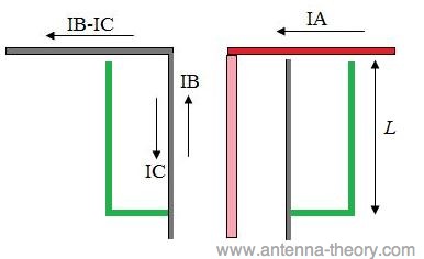
Originally posted by boguslaw View Post
Hmm. Good question. Looks like that is called a choke ring:
Choke ring antenna - Wikipedia, the free encyclopedia
UNAVCO Knowledgebase :: Choke Ring Antenna Calibrations
I do think the same principle can be used in Joulethief / SEC exciter circuits. Just finished a drawing I intented to post in tje JT thread:

Hi-res version: http://www.tuks.nl/img/Lamare_Sleeve_Coil.jpg
The idea would be to use a Hartley oscillator, as I posted before:
Update: Posted some further details here: http://www.energeticforum.com/renewa...tml#post174521Last edited by lamare; 01-06-2012, 10:14 PM.Leave a comment:
-
Lamare,brilliant idea ! This bazooka balun is the missing key I believe .Grids are shorted on one end only.
Is there possible to have more then one bazooka balun one on another ?Leave a comment:
-
Comparing Tesla Tower and Gray tube
Yesterday, I posted some info on the Tesla tower, where I proposed there may have been a structure like a sleeve/bazooka balun under ground in Tesla's actual tower:
Now compare this sleeve/balun thing to Gray's tube and one of Tesla's earlier sketches of his tower:Originally posted by lamare View Post


This suggests that the grids may very well be a short-circuited 1/4 lambda transmission line / balun, such as I use in my longitudinal antenna design, which appears to block any current to flow out at the bottom part of the balun, while it's voltage does vary.
So, if the grids work along the same principle, you would get a longitudinal dielectric (current and magnetic field free) wave propagating from the bottom of the balun, which would be terminal 60.
If that were true, then the central rod would have to be acting like an oscillating coil, whereby the length of the grids would have to be 1/4 lambda longitudinal (pi/2 times as large as the corresponding transverse lambda for the same frequency). If the length of the grids were about 10 cm, then we would be talking about a resonance frequency just a bit over 1 GHz.
If this is the basic operation principle, then you would have to match the length of the wire from the HV capacitor trough the main rod to the spark gap to be some multiple of 1/4 lambda.
I have no idea if this is correct or not, but it may be helpful...
Update: earlier experiments by Tad Johnson a.o. does suggest the use of high(er) frequencies may very well be of importance:
(Tad Johnson) The frequency is adjustable to a degree through adjustment of the spark gap distance and cap size. The caps I am using are 500pF so frequency should be in the KHz range depending on how much amperage the power supply is charging the stack with. Just got the HV resistors today. All I have left to do is build the CSET and figure out the charging circuit. Hydrogen or magnetically quenched gap on the output might be added later for even higher frequency and more protection against current reversals.
[...]
(Tad Johnson) Interesting findings after running the Gray circuit for a couple hours:
ERE does NOT manifest if there is no resistor on the spark gap end of the CSET. Repeat ZERO POWER if no resistor in place. The more resistance, the more the effect appears to manifest.
With 300 Ohm or more of resistance the grid starts to put off a FRIGHTENING amount of power.
Enough to smoke a 50watt, 500 ohm resistor in less than 30 seconds. My input was 12 watts total from the wall. Output from the CSET grid is UNMEASURABLE. Grounding is also becoming an issue since I cannot run the end of the CSET back to ground with a resistor in between. Also, the energy coming off the grid appears to be harmful even with fast rise and fall times contrary to other information out there.
Anyone have any bright ideas on measuring this high amperage, high voltage energy I would be very happy. We need accurate wattage out at this point. I feel confident already with my input measurements.Last edited by lamare; 01-05-2012, 12:59 PM.Leave a comment:
-
Spokane1
We have enough data to make conclusions. Large electrostatic field around device, recreating lightning (which is electrostatic discharge) and huge magnetic field impulse from special custom made coils.
Coils you will find in early Tesla lecture from 1893, powered by single line Tesla currents (commonly known as radiant electricity or cold current).
Kapanadze and Don Smith used the same technique to convert cold current into hot current (from magnetic induction) and this knowledge slowly emerge (from a total mess of disinformation) mostly due to Russian fellows experimenting days and nights like crazy and some brave wise persons here and there (vide Don Smith thread). If you short two kinds of cold currents , strong magnetic impulse is generated, the same if one kind of cold current is shifted in phase and interfence with itself (as Tesla did).Vide various caduceus coil experiments and other very strange coils used nowadays.Power by simplicity.Leave a comment:


Leave a comment: