Announcement

Collapse
No announcement yet.

Gray Tube Replication

Collapse
X
 
  • Filter
  • Time
  • Show
Clear All
new posts

  • Aaron
    replied
    reverse bias triode

    Lighthouse Electric Vacuum Tube Tutorial

    Good simple tutorial on the triodes.

    Here is a reverse bias example with positive potential at the cathode, it is in non-conductive mode and no current can flow.


    Of course this example shows a full connection with anode going back to ground and with the Gray patents, the anode is left unconnected with only a gap to the HV potential.

    Perhaps the HV potential at the HV rod over the gap is enough to attract the electrons to the anode plate in order to be conductive. If that can over come the attraction of electrons towards the cathode where the battery + is at, then maybe it can be conductive and the HV cap can discharge across. I can only see something like this working if there is common ground like the common patents show - that Zetex patent does not show a common ground with the HV side.

    Leave a comment:


  • Aaron
    replied
    triode - thyratron

    Good find Lamare!

    I blew out some thyristors in some experiments early on after Magratten published his experiments - that was before I knew what was going on. I still don't necessarily know what is going on but I think I'm in the right direction. lol

    It seems the self triggering 'could' come from the cathode since there is a positive voltage from the battery there. But with the positive voltage also there from the battery at the cathode, it would seem to mean that there is no ability for current to flow through the triode.

    Of course I'm using the patent reference of how the triode is depicted.

    Here is my old comparison for reference:


    Now just like how a regular diode works, if the positive voltage is on the cathode of a diode, it keeps it shut off and in non-conductive mode. The positive voltage has to be at the anode for that voltage to be available at the cathode - minus the voltage drop of course.

    So on the triode, even if the grid is triggered, with the battery positive potential at the cathode as shown on the right side of the above image, that seems to mean it is reverse biased and in non-conductive mode just like a diode. Therefore, it appears that the battery potential is not going to be available at the anode and therefore the HV cap sees no path to ground and will not even jump the gap to the LV rod.

    The HV can of course jump if it sees path to ground through the triode but seeing that the condition of having the triode forward biased first is a requirement that has to be met first, I don't it working 'yet'.

    And again from the description in the patents, the explanation is that Gray sees the positive from the battery going from the battery, through the commutator, towards the LV rod - only calling it current because it is moving and not a reference to electron current moving from neg to pos.

    "Lines 81~83 states: "This voltage is produced by drawing a low current from a battery source 18 through the vibrator 20."

    That appears to define Gray's terminology that he DOES believe current is moving from the positive of a battery, through the vibrator to the step up transformer. So this seems to be consistent with my perspective of the other diagram posted by Geotron in regards to Gray's reference of how current is moving.

    Lines 101~106 states: "When the commutator current path through the thyratron is closed, current from the voltage source 18 is routed through a resistive element 30 and a low voltage anode 32. This causes a high energy discharge between the annodes within the conversion element 14."

    So, we know 100% for sure that the + of the source battery 18 is available right there at the low voltage rod when tyratron is switched on - of course when commutator also connects the circuit.
    "

    So with this evidence, we know that the battery positive has to be at the LV rod for the HV cap to actually discharge across the gap - and experimentation proves this without a doubt.

    If the triode in the reversed bias mode does not allow the battery potential to be at the LV rod when switched on, then this would be strong evidence, if not proof, that the triode direction in the patent is wrong and that the way Bedini-Cole show it has always been correct. I find it difficult to believe that they got the direction of it wrong after actually examining it. Anything is possible but it is only with the diode in that direction that at least in my experiments that I get anything unusual - the plasma discharge with an accelerated discharge speed of the capacitor and not just a regular capacitive discharge.

    Of course the bottom line is to just do the simple experiment with a triode as shown in the patent to see if the battery voltage is available at the anode when the control grid is triggered. If so, then it is possible that that triode placement is an honest depiction but even if it works - there is no unconventional result that arises from this placement - my prediction.

    I've done this kind of experiment with the plasma circuits with diodes. When battery or LV cap potential is on the cathode, it just keeps the diode in non-conducting mode and the HV will not see path to ground.

    There is an exception to this that would make it appear that the triode/diode is in conduction mode and that is by simply having something conductive hear the HV output from the ignition coil. If you pulse a HV coil for example and have any piece of copper for example, it will give a feeble little spark to that metal since it is finding path to ground through the air. But that of course is of course 15-25 kv at minimum in those coils and not 2kv-5kv in a capacitor, which probably wouldn't do that so I would guess using a HV cap in this range will not spark over unless the triode/diode is truly in full conduction mode.

    I'll have to look more into that inverted mode on the thyratron. The only experience I have with tubes is with pentodes for some special amplifiers I built. They work the same way but all I needed to know is how to connect them so I didn't need to know their operating theory.

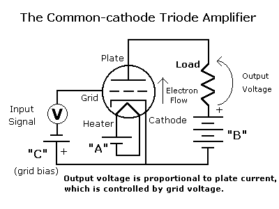
    Basic little triode diagram:


    Lamare, Mark or anyone, what about an SCR? If it is triggered and there is a 12v batter voltage on the cathode, will that voltage be available at the anode? It is basically our triode equivelant isn't it?

    Leave a comment:


  • Aaron
    replied
    green plasma

    Originally posted by Wicaksono View Post
    Hello everyone, after experimenting for a while here are the results that i have, I use 1mm diameter copper wire as electrodes.
    1. Sparks have a purple based color, this comes from ionized air (nitrogen & oxygen). This color is based from electric current : low current will produce purple, bigger current will make whiter & brighter spark.
    2. Arcs from copper electrodes have a green based color, just like Aaron's green arc. This is also have a color based from electric current. The green arc only manifest if during arcing process the electrode is hot enough to vaporize and copper ions get activated by electric current.
    3. To make a spark (without arc) you need to make the electric current goes as quick as possible, without heating the electrodes. This can be made by using a very low ESR capacitor that short-circuited without any resistance.
    4. On the contrary, to make an arc you need to make the current goes as slow as possible to heat enough the electrodes. This can be made by using ordinary electrolyte capacitor (high ESR) that short-circuited with some resistance.

    Wicaksono
    Hi Wicaksono,

    I'd like to say that with my method, the plasma ball is green with every single metal I have used - copper, brass, stainless steel, rusty iron nails, etc... without the inductor, with the same metals and circuit, the plasma is very white - just by adding the inductor, it turns green.

    Leave a comment:


  • Spokane1
    replied

    Leave a comment:


  • Spokane1
    replied
    Thyratrons in the E. V. Gray Technology

    Dear lamare,

    You must have spent all evening doing all that technical research on Thyratrons. I certainly appreciate your efforts. It is work like this that will help solve this import mystery.

    The attached photo is from an old 50's - 60's spot welder. It employs the very same Ignitorn that Gray used and is fired by 2 Thyratrons. For a spot welder the repetition rate is very low. At most 3 Hz. and more typically .5 Hz.

    The GE Gl-7171 Ignitron is the blue can on the left. The two large vacuum tubes in the center are the Thyratrons. This appears to be a cascade approach with the smaller capacity Thyratron (center) driving the larger capacity Thyratron (left of center). The Vacuum tube in the right rear is a HV rectifier with a PIV of about 2500 VDC. The smaller vacuum tube on the right is most likely a Triode.

    These are the kinds of components that I would expect that Nelson Schlaft was confronted with when he was hired to "Make the Motor's Work" in late 1980.

    There were not a lot of cheap solutions to switch HV at the rate and power levels that Hackenberger needed in the 70's (thus the need for the CEST approach). However, these kinds of devices were plentiful on the surplus market. For Hackenberger in the late 70's it didn't really matter if the thyratrons would not be used in the final application. He was attempting to improve the Free Energy Engine and was focusing his engineering efforts in other more productive areas. This part of the circuit could easily be upgraded with newer components in future versions.

    To me this strongly hints that the non-classical conversion process does not take place in these components. To me the CEST was an attempted replacement for the Ignitrons, but didn't work well enough. Therefore the CEST was not the seat of the novel Free Energy creation. But this is just my opinion and not fact.

    For me I'm using mechanical contactors to discharge my storage capacitor for single shot experiments. When I get to the point where I need higher repetition rates I going to upgrade to HV SCR's, provided that they can effectively switch the novel energy particles that I speculate will be stored in the capacitor.

    Mark McKay
    Attached Files

    Leave a comment:


  • lamare
    replied
    Dear Mark,

    Why the postulation of the existence of some kind of "positive particles" before considering phenomena we already know to exist: EM waves (and also longitudinal dielectric waves, for which we also have quite strong indications that these also exist) which propagate at the speed of light (or more) *and* can be connected very nicely to Maxwell's extension of Gauss' law?


    You may also want to take a look at this video posted at a.o. Eric Dollards yahoo group:

    Hello everybody, I have posted a new video showing the propagation of Direct Current through the natural medium, air. I investigate some of the properties and claim Tesla was making by suggesting this mechanism as a way to transfer energy. It is also a good way to see how directional DC sparks looks like compared to AC sparks. That is what we need to aim for when we energize our systems.

    Propagation of Direct Current Through space - YouTube

    Thomas

    Another point to think about is the bandwidth of the transient. We are looking at a spark gap that suddenly breaks down. Now I agree that the sudden break-down is not the same as an arc, but the fact that spark gap transmitters have been shown to operate at frequencies as high as 60 GHz does suggest that a scope with a bandwidth of "just" 300 MHz may very well be far from sufficient to measure the transient:

    J.C. Bose: 60 GHz in the 1890s

    Just one hundred years ago, J.C. Bose described to the Royal Institution in London his research carried out in Calcutta at millimeter wavelengths. He used waveguides, horn antennas, dielectric lenses, various polarizers and even semiconductors at frequencies as high as 60 GHz; much of his original equipment is still in existence, now at the Bose Institute in Calcutta. Some concepts from his original 1897 papers have been incorporated into a new 1.3-mm multi-beam receiver now in use on the NRAO 12 Meter Telescope.
    And also consider what they use Marx generators for:

    Marx generator - Wikipedia, the free encyclopedia
    A bank of 36 Marx generators is used by Sandia National Laboratories to generate X-rays in their Z Machine.
    X-ray - Wikipedia, the free encyclopedia
    Of course, these X-Rays are not generated by the spark gap directly in this Z-Machine, but it is clear that we are most likely looking at a phenomenon with a bandwidth of several GHz.

    Leave a comment:


  • Wicaksono
    replied
    experiments with sparks & arcs

    Hello everyone, after experimenting for a while here are the results that i have, I use 1mm diameter copper wire as electrodes.
    1. Sparks have a purple based color, this comes from ionized air (nitrogen & oxygen). This color is based from electric current : low current will produce purple, bigger current will make whiter & brighter spark.
    2. Arcs from copper electrodes have a green based color, just like Aaron's green arc. This is also have a color based from electric current. The green arc only manifest if during arcing process the electrode is hot enough to vaporize and copper ions get activated by electric current.
    3. To make a spark (without arc) you need to make the electric current goes as quick as possible, without heating the electrodes. This can be made by using a very low ESR capacitor that short-circuited without any resistance.
    4. On the contrary, to make an arc you need to make the current goes as slow as possible to heat enough the electrodes. This can be made by using ordinary electrolyte capacitor (high ESR) that short-circuited with some resistance.

    Wicaksono

    Leave a comment:


  • lamare
    replied
    Originally posted by Aaron View Post
    Thanks Lamare,

    I don't remember if I saw that one or not but it is another Zetex one.

    You can see the overshoot gap 42 is not shorted like they are in the other patents.

    Lines 81~83 states: "This voltage is produced by drawing a low current from a battery source 18 through the vibrator 20."

    That appears to define Gray's terminology that he DOES believe current is moving from the positive of a battery, through the vibrator to the step up transformer. So this seems to be consistent with my perspective of the other diagram posted by Geotron in regards to Gray's reference of how current is moving.

    Lines 101~106 states: "When the commutator current path through the thyratron is closed, current from the voltage source 18 is routed through a resistive element 30 and a low voltage anode 32. This causes a high energy discharge between the annodes within the conversion element 14."

    So, we know 100% for sure that the + of the source battery 18 is available right there at the low voltage rod when tyratron is switched on - of course when commutator also connects the circuit.

    @Lamare - The thyratron looks self triggered.

    Q1 - When commutator is switched on, battery voltage is at the control grid. Is that actually sufficient to conduct between anode and cathode?

    Q2 - Lets say grid is triggered and there is conductivity, will there be battery + potential available at the anode of the thyratron? The positive potential (that Gray calls current) is moving through commutator into cathode and out anode to be available at the LV rod.


    Lines 91~96 states: "When the low-voltage anode 32 is connected to a source of current (battery positive), an arc is created in the spark gap designated 62 of the conversion element equivelant to the potential stored on the high-voltage anode, and the current available from the low-voltage anode.

    What gray means by calling the HV potential is not only a reference to the voltage potential positive as in polarity even though it is + polarity, is it referred to as potential because it is sitting on the rod and not moving.

    He calls the LV current from the battery current even though it is still positive polarity only because it is moving into the rod.

    But the above underlined is telling the whole story. It appears that the entire Ed Gray methodology does simply revolve around the mixing of the HV low current with LV and higher current. It creates the plasma discharge as expected. When the commutator or thyratron is off, the only ground is over the 3rd point or gap to the grid through the inductor back to the battery + or over the overshoot gap to ground on the battery. My demos are exactly this - no different - with the exception of using diodes instead of a thyratron.

    There is however something bogus in the diagram you posted. The HV cap 16 does NOT share a common ground with the LV source and therefore will not arc across when thyratron and commutator are on.

    I don't know too much about vacuum tubes. They don't teach those at Universities anymore...

    Wikipedia has some info on the thyratron:
    Thyratron - Wikipedia, the free encyclopedia

    A thyratron is a type of gas filled tube used as a high energy electrical switch and controlled rectifier. Triode, tetrode and pentode variations of the thyratron have been manufactured in the past, though most are of the triode design. Because of the gas fill, thyratrons can handle much greater currents than similar hard vacuum valves/tubes since the positive ions carry considerable current.

    [...]

    A typical hot-cathode thyratron uses a heated filament cathode, completely contained within a shield assembly with a control grid on one open side, which faces the plate-shaped anode. When positive voltage is applied to the anode, if the control electrode is kept at cathode potential, no current flows. When the control electrode is made slightly positive, gas between the anode and cathode ionizes and conducts current.

    [...]

    Both hot- and cold-cathode versions are encountered. A hot cathode is at an advantage, as ionization of the gas is made easier; thus, the tube's control electrode is more sensitive. Once turned on, the thyratron will remain on (conducting) as long as there is a significant current flowing through it. When the anode voltage or current falls to zero, the device switches off.

    [...]

    Thyratrons have been replaced in most low and medium-power applications by corresponding semiconductor devices known as thyristors (sometimes called silicon-controlled rectifiers, or SCRs) and triacs. However, switching service requiring voltages above 20 kV and involving very short risetimes remains within the domain of the thyratron. Variations of the thyratron idea are the krytron, the sprytron, the ignitron, and the triggered spark gap, all still used today in special applications.

    Here is some info on diodes and triodes:
    Valve Diodes and Triodes

    It says that the reverse current of such a device is almost zero:

    And in this pdf you can see that a triode can be used as a diode:


    However, for use as a diode, the grid would have to be connected to the anode instead of the (heated?) cathode.

    Here's also some interesting info:
    6JD5 Forward grid bias

    It is also possible to operate a tube in a condition called inverted operation:

    Inverted Triodes - The 6AS7/6080 Family
    Inverted Tube Operation

    I will study some of this and think about this some more.

    Leave a comment:


  • Spokane1
    replied

    Leave a comment:


  • Aaron
    replied
    thyratron

    Lamare,

    All the articles, patents, etc... have always said the "key" is in mixing DC with "static" or HV - as the basic principle. Removing the DC mixing with the HV will cause the HV cap to discharge much slower.


    Whatever the case may be, can you comment on this?

    "As far as that thyratron, if it is as depicted in the patent diagrams in the conventional direction, can the battery + potential be available at the LV rod by moving backwards through the thyratron's cathode then to the anode when the it is triggered?"


    [IMG]file:///C:/DOCUME%7E1/MASTER%7E1.MON/LOCALS%7E1/Temp/moz-screenshot.png[/IMG][IMG]file:///C:/DOCUME%7E1/MASTER%7E1.MON/LOCALS%7E1/Temp/moz-screenshot-1.png[/IMG]

    Leave a comment:


  • lamare
    replied
    Originally posted by Aaron View Post
    Ok, I think it is just like I said earlier.

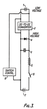
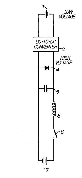
    First, battery 1 charges the hv cap through the converter.

    When HV cap is charged, switch 6 closes.

    When switch 6 closes, that activates switch 8 which essentially puts the positive of battery 1 at the anode of diode 4.

    As soon as that happens, the mechanical switch (which is what 6 looks like) conducts the HV over it towards 7 recovery battery and simultaneously, the LV + goes through the diode and follows the HV through the inductor over the switch and to battery 7. The current in battery 1 is obviously then going backwards through the circuit through the switch and through the inductor.

    What this diagram shows is that Bedini is right about the diode placement being in reverse. Why?

    When switch 6 is closed, the diode 4 is the same as the diode at the LV rod in the tube - it absolutely is because look at the battery 1, it's positive is connected to common ground which is exactly at the diode 4's anode. There is no difference from the tube setup. This diagram shows the truth.

    Switch 6 closes and when battery 1 + is at the diode 4 anode, the hv from cap 3 has 2 paths. Towards the cathode of diode 4 or towards the inductor. Diode 4 shuts off and hv cap 3 can only go through inductor 5 and switch 6 to recovery batt 7. And LV battery mixes with the HV through the inductor.

    I'm just thinking out loud here, but what this shows me in my opinion again, is that this shows the diode is supposed to be reversed at the LV rod in the tube like Bedini shows. I'm of course open to correction but this diagram is simply another variation of mixing the hv low current with lv and high current.

    Look at battery 1. The negative is bypassed around the converter so that it shares common ground with the rest of the circuit - a current path to go backwards through the inductor when switch is closed. It appears switch 8 would just short battery 1 to itself but the positive I believe will go through the diode 4 and through the inductor.

    It is spelled out in figure 1 & 2 in that application. The + of the battery 1 goes through switch 8 and then through diode 4!

    I think the basic principle of this circuit can be reduced to this:


    When the switch closes after the HV cap has been charged, what happens is:

    1) You get a (HF) transient, a sudden (large!) change of voltage on one of the terminals of the coil, with an extremely short switching time, because of the use of a mechanical switch which also forms a spark gap just moments before closing.

    2) This transient gives you a shockwave, generating a wave with an extreme dE/dt propagating (with the speed of light or so) along your coil windings, which on its turn energizes the coil by generating a magnetic field along Maxwell's extension of Ampere's law:

    Ampère's circuital law - Wikipedia, the free encyclopedia

    3) Current starts flowing (within nano-seconds or so after closing the switch, but *after* the transient shock wave already energized the coil), whereby the HV cap discharges trough the coil towards the battery.

    4) Now the coil has been energized by two sources (transient wave and HV discharge) and therefore the (B)EMF will contain more energy than expected when considering only the energy contained in the HV cap.

    5) (B)EMF maintains the current in the direction it had before, trying to discharge the HV cap. When the voltage on the HV cap becomes 0 V, the diode prevents further discharge of the cap and the coil continues to charge the battery trough the diode. This way, all the (B)EMF energy contained is used to charge the battery.


    And if this is the basis principle, then you would expect problems arising with the switch, especially when you scale this up to an engine delivering considerable horsepower. The contacts of the switch would wear-out pretty fast, resulting in problems with timing, etc. And then you may end up looking at special high-current spark gaps, which you somehow trigger, which may also be what the CSET is for, as I suggested earlier.

    Leave a comment:


  • Aaron
    replied
    thyratron

    Hi Mark,

    So far on the experiments I did, I couldn't see a different with or without the tube. If the tube was supposed to be filled with nitrogen that gets ionized and conductive to conduct the battery over to the grids then the nitrogen atoms recombine to stop that conductivity and shut if off abruptly - or something like that to increase impulse speed, then there may be something to it but I guess there is no evidence of that.

    The rotating spark gap is something I want to try on my ignition method with an inductor to see what a difference would be.

    As far as that thyratron, if it is as depicted in the patent diagrams in the conventional direction, can the battery + potential be available at the LV rod by moving backwards through the thyratron's cathode then to the anode when the it is triggered?

    Leave a comment:


  • Spokane1
    replied
    Opinions on New CEST Schematic

    Originally posted by Aaron View Post
    Geotron,

    And I'd like to get Lamare's comments on the Thyratron - or Mark's if the LV + from the battery potential will be available at the rod if the thyratron is triggered and the LV goes into the cathode and out the annode - or is it directional, which would prevent the battery + from being available at the rod.

    Leave a comment:


  • Aaron
    replied
    common ground missing

    Geotron,

    I think fig 1 can't be properly understood if there is not a common ground the HV cap share with the LV source batteries.

    If you only have HV coil discharge without a cap - it WILL jump the gap to the other rod because it is finding ground through the air - most people experience this with a simple ignition coil, which will spark to an object - a weak spark but a spark nevertheless because it finds ground through the air. But that is not enough to give this HV cap in this circuit a real discharge.

    And I'd like to get Lamare's comments on the Thyratron - or Mark's if the LV + from the battery potential will be available at the rod if the thyratron is triggered and the LV goes into the cathode and out the annode - or is it directional, which would prevent the battery + from being available at the rod.

    Leave a comment:


  • Guest
    Guest replied
    In reference to GB2031665A,

    This system shown in Figure 1 has the rectifiers on the LV anode such
    that pull is generated on the cathodes of both the source and recovery
    batteries; a reverse flow mechanism?

    It seems highly different to the schematic of our systems, for which are
    provided only a bank of enough diodes to block the HV pulse from the ignitor.

    Might the items 26 and 28 instead be an SCR switch positioned before a
    blocking rectifier? With a HV level not exceeding 5KV, it seems as though
    the system would use two banks of five 1KV rectifiers, one for the item 28
    and the other at 46.

    It seems unclear what effect is attained by combining the fullwave
    rectifier 24 with the halfwave 44 into the HV capacitor.

    Leave a comment:

Working...
X