this is a dead link on my end
all dead links
http://www.energeticforum.com/renewa....html#post7525
http://www.energeticforum.com/renewable-energy/962-use-tesla-switch-7.html
and about 10 more dead links that make proving stuff laughable.
You don't need to convince me you need to help the people following Tinman who absolutely makes a wreck out of every free energy replication. Like John Bedini pointed out all the years of his existence here on this earth " sure if you took his machines apart they do not work"
Tinman always leaves out a part or he dismantles the idea. Here is Tinman making fun of the 3 battery systems. He has 4 video's but never uses the Matt modified motor in the circuit. Yet everyone quotes Tinman as gospel. What a shallow bunch who have small reasoning abilities.
The Matt motor will give a cop 1 as long as you work to tune it but you need a generator connected to it and to my knowledge there is no such setup on the internet. Just he said they said they thought we had it close to cop 1. In other words nothing conclusive to back it up.
So for now Tinman is the only one.
Announcement
Collapse
No announcement yet.
Motor Generators
Collapse
X
-
Matt's motor run the way it is shown in the video does nothing special. I would absolutely agree. The power generated by the motor fights the input from the source as CEMF, back EMF or whatever you want to call it. Probably LESS efficient than a whole LOT of motors because the efficiency to run the way it was run in the video was decreased when it was modified.
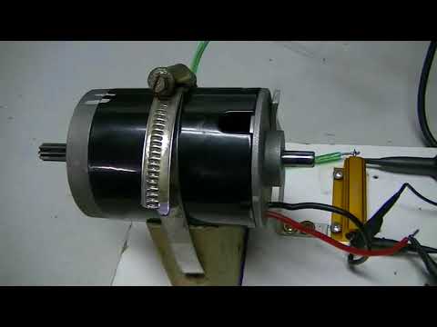
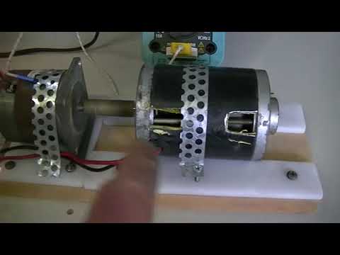
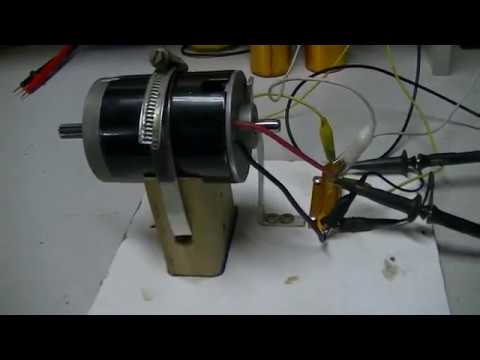
But the Matt motor was not DESIGNED to run directly on the positive and negative of a power source. If run BETWEEN THE POSITIVES as it was DESIGNED to do, it allows the CEMF as well as the coil collapse to travel A PATH OF LEAST RESISTANCE, which is INTO THE CHARGE BATTERY on the 3 battery system. What this does is help to CHARGE the 3rd battery, and if the batteries are properly rotated, you get longer run times than if run in a standard configuration. Run on the 3 battery system, it is a winner. Run on a single battery or two batteries in series, it is inefficient. Hint: When you ground a motor to run it, BOTH COILS will create BEMF. This energy has to be disapated before current will flow. Reducing your actual flow time, and amount of flow. Also reducing the amount of energy actually doing work. When watching the OUTPUT side of the motor run between the positives, you'll see 2 occilations. One is clear and obviously an ON/OFF wave. The other rises then falls but has both positive and negative spikes indicating BEMF. Depending on what side of the motor is powered and what polarity of current is used, the wave changes.
The Matt modified motor is PART of a SYSTEM that allows you to build a COP>1 device, but it is not such a device in and of itself. There are losses in the motor and tremendous losses in charging a battery due to impedance. Unless a POWER GENERATION ELEMENT is added, you cannot achieve COP>1. So it does EXACTLY what it was designed to do, but hey, believe what you want.
Here is the data from Matt's build, not mine. I built a much smaller version back in the day when I was working away on Tesla Switches. Conclusions were, to produce SERIOUS POWER, it works, but Solar is CHEAPER:
4 batterries in Parrallel = 56 hours of runtime
Same 4 batteries in a Tesla switch = 432 hours of runtime 432 / 56 = 7.714 times longer runtime.
Motor runs at or up to 100 watts AND PROVIDES SHAFT POWER.
Under Tesla the same motor only cost you 12.96 watts to get the same work done. MUCH of the input energy is RECOVERED in the charge batteries. 80+%
$ Battery setup with motor.png
If you want an education on running between the positives you could go here: http://www.tuks.nl/wiki/index.php/Ma...nesTeslaSwitch where some of Matt's info has been collected, or you could go to the "Use for the Tesla Switch" thread on THIS forum. It's a really long thread. Really long. So make plenty of popcorn, and get a haircut before you start. One thing I will be very clear about. Replicating someone else's work means replicating EVERY part of it. I watched guys on the forum run this stuff at the wrong switching speeds and it doesn't work worth a CRAP. Matt didn't give EVERYTHING away, but he showed enough that anyone with a SERIOUS INTENT who would stick with it, do some actual work on their own, and not whine like a baby that needs to be spoon fed, would see results eventually. I think he discusses frequency on the page I linked to above. Anybody watch Peter Lindemann's videos and presentation on the Benitez Tesla Switch? One of the things Peter states is that what is left out of the patent is an "interruptor". Something that breaks the circuit and allows for a voltage spike. Guess what the Matt modified motor DOES among other things? Since it has commutator sections that are NOT connected to the coils, I'll let YOU figure it out.
Anybody here ever built Matt's "simple motor"? Not the Matt modified Razor Scooter motor, but just his "simple motor". If you haven't, you SHOULD. Really should. Really, really should. It is the motor in the "motor" position on this schematic, and has some advantages that the Matt modified motor does NOT, while still having all of the advantages of THAT motor. And it is easier to build, although pricy if you don't have magnets lying around and a spool of the right wire.And rotors. Worth it though. I did NOT build the circuit shown here, so the performance claims are Matt's.
I DID build a very similar circuit Matt designed with TWO coils, TWO batteries, TWO rotors, as the motor, and kept the batteries charged. Bob French and I are building THAT particular setup again, just because a motor that runs all the time without running down the batteries might come in handy, even if it only turns at 2-3,000 rpm.Last edited by Turion; 03-31-2022, 07:53 AM.
Leave a comment:
-
-
I thought some of those things too. However I found that my "C" core having a core pole on each side responded the way I posted. So using the Rpm and having 10 magnets going 1700rpm my frequency meter gave me the answer.Originally posted by Turion View PostI thought it was cycles per second, as in both a NORTH and a SOUTH = a cycle. Is one magnet hitting the coil a cycle, or is it a North and then a South hitting a coil to make a cycle?
Just asking. I have no idea.
I was running approx. 280hz on my coil with 10 magnets whipping 1700 revolutions' Per Min
This is 17000 times flux transferred into the core material each minute 17000 divide 60 seconds = 283hz
I experimented and read the meter
yes I guess not. Like you always say the bench don't lie. I was thinking double that.
Last edited by BroMikey; 03-29-2022, 10:53 PM.
- Likes 1
Leave a comment:
-
I thought it was cycles per second, as in both a NORTH and a SOUTH = a cycle. Is one magnet hitting the coil a cycle, or is it a North and then a South hitting a coil to make a cycle?
Just asking. I have no idea.
Leave a comment:
-
This is how frequency is determined.Originally posted by Turion View PostAnother thing to consider is you could have 24 magnet rotor with 7 coils on each side of the rotor (14 coils). The frequency would be 7x24 = 168 x rpm. And you have to match your voltage to that.
24 magnets cycling at 2800rpm =24 X 2800 = 67,200 times per minute the flux will strike a single coil core. But you want frequency, not pulses per minute so for this we need to go to a per second number. To do this divide 67,200 per minute by 60 seconds because we know that for every minute of time there are 60 divisions.
67,200 divided by 60 = 1120 pulses per second also known as 1120 cycles per second or 1120hz. Each section of core material found inside each coil gets struck by the same number of pulses as all 24 magnets pass by.
Therefore each of your generator coils will produce 1120 hz AC
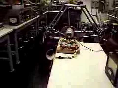
For fun I am throwing in 2 video's (some old footage)
Last edited by BroMikey; 03-29-2022, 08:35 PM.
Leave a comment:
-
Another thing to consider is you could have 24 magnet rotor with 7 coils on each side of the rotor (14 coils). The frequency would be 7x24 = 168 x rpm. And you have to match your voltage to that.
Leave a comment:
-
I buy my cores from these guys and charts tell you how many turns of awg wire size for a job. call them they help
Custom Toroidal Transformer Solutions For All Industries. Bridgeport Magnetics is your trusted source for high-quality toroidal transformer solutions.
https://www.bridgeportmagnetics.com/...-transformers/Last edited by BroMikey; 03-29-2022, 11:37 AM.
Leave a comment:
-
Unless I am way out to lunch, the V/f ratio is what must remain constant, so a 60hz or 100hz transformer can be used as long as you wind the COIL to produce the correct voltage for the operating frequency. Even if you get everything wrong, all that happens is losses and heat. You still get usable output from the transformer. But then, I'm no expert.Last edited by Turion; 03-29-2022, 07:58 AM.
Leave a comment:
-
Not using transformers rated at 60hz you can't. A toroid wound right maybe but I am not sure you can do that. The right toroid core rated at 2000hz could be wound for step up or step down. Hanging a 60hz transformer on it won't help you so converter first yesOriginally posted by Turion View Post.Everything can be run into bridge rectifiers, converted to DC and then stepped down to 12, 24 or 48 volts.
Or you can first run through an AC transformer to up the amps and step down the voltage and then bridge to DC.
It has kept me busy and out of trouble I know I would have gotten into otherwise. Big trouble. Life changing trouble. LOL.
So the problems with the new machine are as follows:
1. The rotor magnets are not powerful enough
2. The coil MAY not have a big enough core
3. The coil MAY not have enough winds
4. The coil MAY not have enough strands.
5. The current machine will not hold coils of any larger diameter than what I have now.
Sounds like bad trouble running with the wrong crowd.Last edited by BroMikey; 03-29-2022, 02:45 AM.
Leave a comment:
-
We have discussed the coils. It is really the watts output per coil that matters, not the volts or amps. Everything can be run into bridge rectifiers, converted to DC and then stepped down to 12, 24 or 48 volts. Or you can first run through an AC transformer to up the amps and step down the voltage and then bridge to DC.
I much prefer solid dependable DC output with plenty of amps because it can be used to charge my battery banks or run inverters. AC output that is NOT at 60 Hz can be problematic if you try to run some things directly with it. Warranty voided!
I can see that a 1” by 1” N52 magnet and a 1” diameter coil core would probably produce all the volts and amps we are looking for with the correct coil. I am looking for bobbins with that size core now as I wanted to try the bigger core anyway. I am really curious to see what size magnet and then what size coil core it will saturate.
I guess it’s time to do some research. I am sure that specific core materials probably have formulas for saturation, especially if they are designed as core materials. You have to saturate the core before you can wind a coil that will put out max power for the specific magnet and core mass (quantity) that you have. A magnet that is too small for your core doesn’t get the job done and one that is too big gets you no “extra” volts or amps.
$325.00 a month x 12 months x however many years plus an extra $100 every year I got from my in-laws at Christmas has been my operating budget, so I’m probably at the $50,000 mark now. But that includes lots of equipment I have bought for my shop that has gotten used on tons of other projects from Bedini motors to Benitez style Tesla switches, woodworking projects and cabinet making. Desktop CNC machines and 3D printers. It has kept me busy and out of trouble I know I would have gotten into otherwise. Big trouble. Life changing trouble. LOL.
Leave a comment:
-
Sounds like you will be getting your answer so the new cores will work instead of all that heat. BTW Thanes rotors use 1" dia magnets by 1" long. However I would like to add he runs 3600-3700 rpm and targets 70vdc with higher amps such as 3-5amps per coil. So half the voltage you run and twice the amps. Thanes coils may be able to go to 5amps but 3 amps all day long is better for those specific designs. You never run max values.Originally posted by Turion View Post
I hope I have the data necessary to compare these other small rotors to my original rotor with some accuracy.
This allows me to test magnets that are
3/4" diameter by 3/4" thick
1" diameter by 3/4" thick
3/4' diameter by 1" thick
1" diameter by 1" thick
2' diameter by 1/4" thick
Because I will not be using a coil holder, I can build a coil that is bigger in diameter than what my current machine will hold. The plan is to see what output I get
This is food for thought only. Thane is always changing coil sizes to see what is possible. See the last pictures I posted of his 3 coils that are various sizes. It seems that this type of coil is the same length for everyone at high speeds.
Longer coils give high voltages and sacrifice Amps. Sorter coils give less volts and much higher amps. It may be better to run higher amps, I can explain why.Last edited by BroMikey; 03-28-2022, 11:21 PM.
Leave a comment:
-
Thanks Dave regardless of our differences you have always come thru with the bacon, sharing your progress and hard knocks. For that you have my respect. You are so blessed to have people helping you and based on your post have a new adventure ahead of you even if the old units were somewhat disappointing.
Your new setup sounds great to me and this is exactly what THANE HEINS did for years. In his first 10 years of testing all you see is another bench grinder with rotor magnets, sometimes dual rotors. If you are not careful you will end up spending $100,000 in total after all these years like he did.
I know how it must feel with the new machine being a failure. That's to bad, I am sorry to hear that. I wish you could use the rotor to connect to a bench grinder but then you wouldn't be be able to put it together again.
Update: My open heart surgery is healing fast, it has been almost 3 weeks and now I sleep most of the time. Blood pressure is awesome, just have to readjust.Last edited by BroMikey; 03-28-2022, 10:51 PM.
Leave a comment:
Leave a comment: