
 Tweet
Tweet
Originally posted by Ufopolitics
View Post
-
-
Serious Geometrical Error(s)...
Mark,
Why you complicate yourself so much?
It is so simple to look at without ANY Commutator nor Brushes.The Commutator for this Motor is based on 56 Elements, NOT 28....Therefore, every Single Pair must attach to TWO Elements.
But this fact does not matter here, we are "fitting" the real magnetic interactions from Rotor within Stator configured Angles.
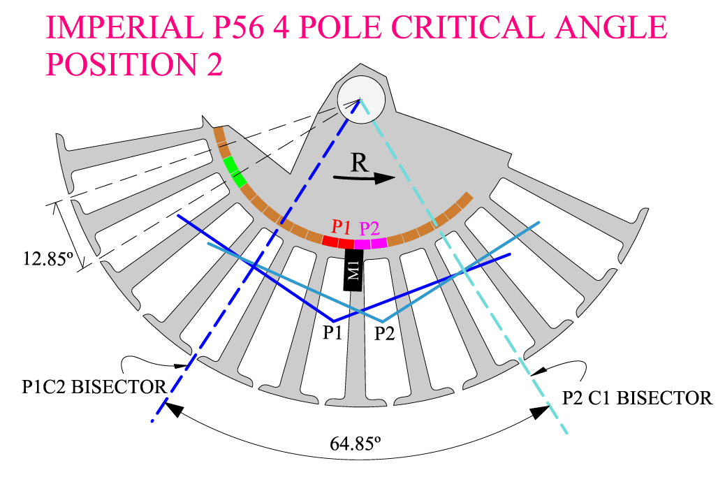
Rotor MAX Interaction Angle based on Two Pairs being fired at same timing
 [/IMG]
Switches are VERY Relative here, We could install them anywhere... like shown above... Brushes turn, wires expand and reach connections to Comm elements...Commutators turn ...above setting is right at center of Pair Intersection...the MAIN SIDE To Observe here are the MAGNETIC INTERACTIONS taking place between Rotor Coils and Stators.
The only thing the switches are supposed to accomplish...is to Disconnect or Connect when they are commanded to do so.
I have set different positioning of brushes and comm elements here related to every machine different configuration settings...choosing the position would be better to adjust without major complications...making it simple for building.
This confusion you are showing...all is doing is confirming that all your previously built motors have also, something very and seriously wrong within their interactions/timing settings...reason why all your under performance readings.
However, I admire the fact that you DO have the 'audacity' (not to say the balls.. )... to start shooting at me,the bringer of this type of winding...and who have a few naked, Imperial Rotors in his Garage...plenty of wire and many, many Geometrical Angle Rulers, and software CAD'S , HD Cameras to demonstrate you ARE WRONG...
Please, think about all this...and do not waste my time insisting now on a Motor Structure you have not even started to work with...?
UfopoliticsLast edited by Ufopolitics; 05-02-2015, 09:16 PM.Principles for the Development of a Complete Mind: Study the science of art. Study the art of science. Develop your senses- especially learn how to see. Realize that everything connects to everything else.― Leonardo da VinciComment
-
UFO!When you have 2 coils which have 4 coil sides and it is obvious that 2 of those coil sides cancel each other out, it is a no brainer to eliminate those 2 coil sides and go with a single coil of twice the span.
A Single Coil would have much less "span angle" or as I call it Throw Out Angle. You can not just use one single coil and wrap it around EIGHT POLES of that Rotor, it is too wide of a semi air core, half and half steel and air desig
6 poles coil for the A1MoGen = "singular coils" will be close the RPMs of the Pair Winds and 7 poles might be faster... "span angles" is not very important because the RPMs are almost the same.
*TORQUE*
ALSO the singular coils = A1MoGen will have around 30% - 40% MORE TORQUE than pair wind... Torque is very important.
FACT: The A1Mo-Gen = singular coils wins huge in toque!
Keep it Clean and Green
Midaz
Cat & MouseLast edited by Midaztouch; 05-02-2015, 11:46 PM.Comment
-
Twice you reinforce the point that P2 must be FULLY Disconnected.Originally posted by Ufopolitics View Post
We agree on the rotor geometry angles.
We agree on the stator geometry angles.
Agreed. The leading edge of the comm segment connects on one side of the brush and disconnects when the trailing edge of the comm segment leaves the other side of the brush. The brush width has to be considered in the equation because P2 has to advance over the brush before it can FULLY Disconnect.Originally posted by Ufopolitics View Post
Please do not see this as shooting at you. It is important for others to understand these interactions. As a novice those many months ago I didn't realise this simple truth. Fortunately I wasn't designing motors, I was building them to pattern. Now I'm designing configurations and testing performance.Originally posted by Ufopolitics View Post
Your quotes above make it clear that the 'ON' time starts from P1 just connecting to the brush to the time when P2 is fully disconnected from the brush. It is self apparent within those two criteria that the angle for P2 being on the brush MUST be added to the critical angles between the two relevant magnet bisectors.
I have been repeatedly accused of being unable to time my motors because I am confused. The simple fact is this...these factors are out of everyones control. All comm segments, in principle, are connected to the brush from the leading edge of the comm entering the brush to the trailing edge leaving the brush.
Hunting
markComment
-
Yes that is just great we agree on those points-angles.Originally posted by HuntingRoss View Post
It was a 'typo', you are correct it is P1C2
Yes, great we agree again...
Ok, so it was good enough having three agreements in a raw...now I disagree with you.. ...because you are just adding the 'switcher displacement angle' to the magnetic interactions angle...just because the "switch" is outside the 64.85 degrees from the EM Interactions taking place.(see image below as the one you are referring to):
[IMG]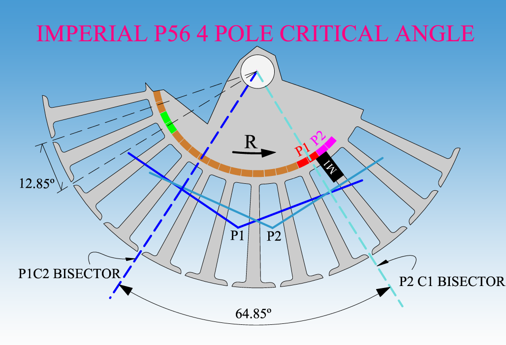 [/IMG]
Let's stop 'jumping' from 28 to 12 poles Machines Mark...pls...let's keep on the 28 poles Imperial.
So on Image below...I want you to do your Math, the same "method"...and tell me the total angles that we have to adjust timing there...Obviously you overlook this image because I have uploaded on previous post, and you did not quoted at all...
[IMG][/IMG]
What about another commutator element connection from P1-P2 terminals?...plus brush rotation to meet the desired timing?
See below Image Mark...a closer approach to original argument-discussion,
[IMG]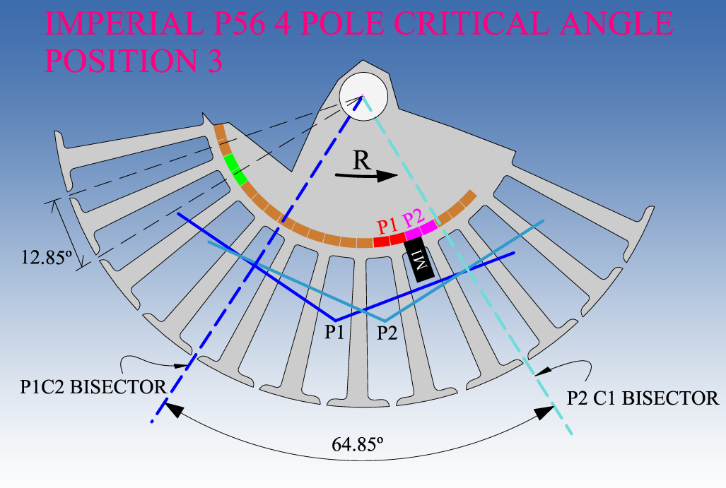 [/IMG]
Now...are you still adding the Comm Element plus Brush displacement Angles on the Two Images above Mark?
What I want you to note by those Two Images (actually all three) above...is that the switching angles could be moved within an unlimited area regardless of the EM Interaction Angle, (not affecting it at all) so...could be after (post), within (Aligned to EM) or even before (pre-retarded) to our convenience, however, the EM Momentum displacement still, will be taking place within the specific/required Space/Time, which is actually THE SAME for All Three Images on this Post...
We are just changing "around" the "Switch" position, by stretching the connecting wires just 'a bit'...then moving the Brushes to meet those contact plates...
It is a completely relative "item"(the switching circuit)...just like we could set the actual, physical ON-OFF switch... anywhere we decide in any electronic/electric device or equipment...
Just hoping to have the 'final agreement'...
UfopoliticsLast edited by Ufopolitics; 05-03-2015, 01:24 AM.Principles for the Development of a Complete Mind: Study the science of art. Study the art of science. Develop your senses- especially learn how to see. Realize that everything connects to everything else.― Leonardo da VinciComment
-
Tuning Test Results GM QUP-10 embodiment
No magic bullet found so far in Quad Stator embodiment. I was looking for the spike down in amperage as found by GChilders in his dual stator 5-pole conversions.
Review: This motor is built out of GM window regulator components into an aluminum 2' pipe, converting it to a Quad Stator. The rotor is a 10-pole and is wound using trifilar 32ga wire, with the coils coming in at a calculated 1.22 ohms, using 6'/ohm metric for for 32g wire. each coil had about 22' of wire. End plate construction allows tunability only constrained by brush wire length, as the brush wires must exit thru the motor body as opposed to the endplate, since the quad brushes took all available real estate there. I found I am able to avoid higher temps at the brushes, with lower amperage with the extra .2 ohms. As it has broken in the amp draw has dropped and the rpms risen, now maxing out close to 7000 and the brush temp about 122degF.
Test picture shows optimum performance at 11.6v, 1.58A, using a 60w 12v power supply. Two of the 4 brush sets are receiving power.
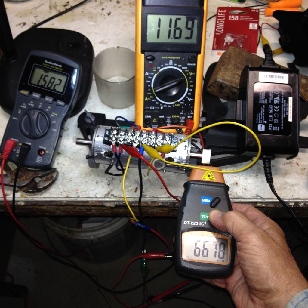
Using Ufopolitics wiring diagram to display results:
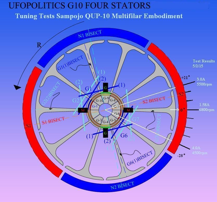
The zero degree position is Ufo's recommended setting on his diagram. From there I notched 1/8" hash marks, 4 on one side in the direction of rotation, and 3 opposite to rotation. This is approximately 7 deg. per mark. I found pretty much a smooth degradation from optimum as I moved away from the 0, "zero" setting.
Findings: Amp draw increased proportionally and rpm dropped as tuning was adjusted away from the initial position. Although amp draw increased a factor of 2 and 3 times as tuning was moved 21 and 28 deg away from optimum, No factor of 10 or more improvement was found.
PS: tried a few 1/2 hash mark positions also, no suprises.Last edited by sampojo; 05-03-2015, 07:25 PM.Up, Up and AwayComment
-
Your analogy to electric circuit is flawed.Originally posted by Ufopolitics View Post
copied from: 6.3 - Magnetic Force and Field
I don't understand your reasoning. Two magnetic South poles repel and so do two negatively charged particles (repel).
Sparks are caused by potential difference or voltage. I don't know what you mean by _Negative charged end terminals_, but if the two conductors have little to no potential difference, they will not arc as they are brought together to touch.Even more simple...Two Negative charged end terminals will NOT do absolutely NADA...not even a very dim spark when making contact..Last edited by bistander; 12-02-2019, 09:44 PM.Comment
-
Free Speech
You are wrong Ufopolitics. I have the right to free speech. Even though you may consider ancient laws unworthy, the US Constitution and First Amendment trump you. Those who seek to shut out dissenting views and limit the speech and expressions of others who disagree with them often become tyrants. Don't let this happen to you.Originally posted by Ufopolitics View Post
I went through this twice, but again for you. Yes, the 2 coil sides in the same armature slot cancel;Originally posted by Ufopolitics View Post
1 - Magnetic field for those two coil sides.
2 - Electric field for those two coil sides.
3 - No, current will still flow through those two coil sides. It has to to complete the electric circuit. And that is the problem. You have current flow through copper and associated resistance which does no work for you.
But that is exactly what you end up with with your coil pair because the inside coil sides (sharing the same slot) cancel each other magnetically. So the coil pair will behave just like the double wide coil.Originally posted by Ufopolitics View Post
I was talking about the electric dynamo. And the electric generator can be powered by hydro or wind turbines without any objectionable farting. This is the renewable energy sub forum.Originally posted by Ufopolitics View Post
I really don't want to argue with you. So just drop it. I simply saw an obvious way to improve an armature winding and posted it. You have an empty core there. Give it a try. If it works, use it and develop your own theories as to why.
biComment
-
SampojoOriginally posted by sampojo View Post
Thank you for your findings. I was hoping that you found amazing test results like Gary's "sweet spot". Was all if the timing adjustments done under No Load?
Bistanders is debating Raul/UFO on "Coil Magnetic Efficiency". Just like me, Bistander is saying that the Singular Coils are best for Asymetric Motors . Singular Coils is exactly how I made the A1MoGen. If you decide to build your motor with the Singular Coil design. Use 4poles singular coils for you motor. You will have more TORQUE, higher RPMs & less voltage drop.
Tesla was an efficiency purist. He would've done it with Singular Coils.
Keep it Clean and Green
Midaz
UFOs and flying Unicorns are still myths. Looks like DADhav was correct. Gary, where is your proof or are you gonna disappear again!?Last edited by Midaztouch; 05-03-2015, 10:38 PM.Comment
-
Originally posted by Ufopolitics View PostAgreed. The leading edge of the comm segment connects on one side of the brush and disconnects when the trailing edge of the comm segment leaves the other side of the brush. The brush width has to be considered in the equation because P2 has to advance over the brush before it can FULLY Disconnect.Originally posted by Ufopolitics View PostOriginally posted by Ufopolitics View PostOriginally posted by Ufopolitics View PostComment
-
In your video you state the motor is achieving around 150 rpm/volt.Originally posted by Midaztouch View Post
Now whilst I don't agree fully with the concept, most on this thread are adopting rpm/watt.
On that basis, from your 20v DC PSU test -
150 rpm x 20v = 3000 rpm
3000 rpm / 420w = 7.14 rpm/w (no load)
Not allowing for frictional losses and so on. With a sprocket ratio of 3:1 your rear wheel will be 2.38 rpm/w (no load).
Hunting
markComment
-
MarkOriginally posted by HuntingRoss View Post
Don't adress me again... A 16awg coil wire got stuck = HIGH FRICTION = high AMPs, between the rotor and magnets during transport on my Bicycle. (That's why I said "I can show you 150 RPMs... ANYTIME and its CONCRETE", in my video.)
Me going to the Meiwa Electric was all about A1MoGen & Asymmetric Motors on a DC power supply for validity...The motors work fine on a DC Power Supply if the timing is correct.
Your a waste of time for me! You never listen or pay attention to anything.
Midaz
It seems like Raul/UFO is wasting his time telling YOU the same thing, over and over ....
To avoid the conversation about torque, RPMs and voltage drop with the Singular Coils = A1Mogen -vs- pair coilsLast edited by Midaztouch; 05-04-2015, 12:55 AM.Comment
-
Weak Legs
Hello Bi and everyone.Originally posted by bistander View Post
After reading a few of the recent posts I thought I'd add some food for thought. I think It was Bi who mention empty cores. I assume that means an armature leg with now wire around it. I've always had that concern but when I first started designing and winding motors there was a very popular three phase wind used on model airplane motors that was known as the LRK wind and for a number of years it remained popular and was not improved upon until some of the later day motors. the wind had stator legs left unwound between the three phases as below.
I'm not siding with anyone here but there are many things that worked about this wind. I myself don't care for it and prefer no overlapping winds as well as no winds around more than one stator / armature leg at a time. With that being said has anyone here ever tested how much magnetism is found on the outer diameter of the your armature when the brushes are energized. I think you might be surprised at how low it is compared to your field magnet. It might also be much lower than what it could be if each leg of the armature was wrapped completely around. If that's what Midas did and kept the same wind as UFO suggests with a multiple leg wind then maybe that's good. As for me, I'm still waiting to see a test including loading that shows an improvement over the OEM. Speed alone means nothing to me. I put my money on the turtle not the rabbit.
Good luck everyone
JComment
-
Sir JOriginally posted by DadHav View Post
Nice to see you around here again!
This is what I did with the A1MoGen design. The Singular Coils are the same size as the magnet or a little bigger for higher RPMs.
Empty Core = middle slots with no wires of the coils being energized.
[VIDEO]https://m.youtube.com/watch?v=0AwYKpdmYa4[/VIDEO]
Keep it Clean and Green
MidazAttached FilesLast edited by Midaztouch; 05-04-2015, 12:48 AM.Comment
-
-
Hunting GChilders;-)
Yes I just look for max rpm no load, min amp draw. No way of controlling torque load consistently in my basement labOriginally posted by Midaztouch View Post. But I don't see a lot more revealed in that. After seeing Garry's numbers, who I believe is a serious researcher, I am looking more at reproducing those numbers myself. After all it would be the mother load of free energy? Tesla's original energy multipliers he had in Wardenclyffe?
What has got me intrigued,assuming I did not miss an adjustment, is the question, "Is there a simple reason I did not see the drop-off of amperage in my motor?"
One major difference is quad stator vs. dual stator. I may either have to roll out my old radio shack conversions or make my dual stator GM motor tunable. Thats a big job.
Or get on to my Baldor 56 frame motors, which are dual stator, completely infinitely tunable.
Question for Garry: Just to confirm it appears you moved one notch off the Ufo recommended timing Position?
I guess its in his video, just need to rewatch as to whether it is before or after Ufo's recommended Top Dead Center timing mark.Last edited by sampojo; 05-04-2015, 03:31 PM.Up, Up and AwayComment


 ...but they further on 'concluded' without any substantial proof that the FLOW will take place FROM NORTH TO SOUTH...as seen the arrows above following a ONE WAY direction...

Comment