
Originally posted by sujan_ms
View Post
-
project on tesla switch
hey jeff i just saw your inverter 2 cap pulsator its very cool. im interested in taking up this idea as my final year project . im doing my ENGINEERING.Originally posted by Bit's-n-Bytes View Post
we are group of four people, me and my three other friends, i wanted an explanation of the circuit , in the lower most left corner of the circuit i found something which i didnt understand, can u just tell me what it is.
is it some kinda of coil (heat sink)....???
I also need to know some things l ike whats the purpose of the inverter in the circuit, what does the switching circuits do.
should i use a A/C transformer i.e 12v A/C to 52v A/C ???
PLEASE HELP ME OUT.
regards sujan
Leave a comment:
-
Hi there Lamare,Originally posted by lamare View Post
This is only partially true. To maximise the effects of "recovered" energy one must also just capture the energy in one direction only. A point completely missed over the years that this thread has persisted. So, what you should add to your circuit is the isolation of the pulse without its negative return. You only want the positive aspect of the pulse - IMHO, the simulation of an electrostatic pulse. The tops of the pulse - this is the manner with which items such as the Kromrey Converter operate successfully and do not work for those experimenters that do not understand this important concept of energy separation.
I see that Mark contacted you, hope the connection proved useful.
regards
RobLeave a comment:
-
Thanks Ash. Been very busy working more great devices. Shipping now is the new generation Rejuvenator. This puppy works great. The production Battery Swapper is just around the corner. We have designed the new case and started the assembly. There also might be a "Next Gen Tesla Switch" coming to a conference soon! Stay tuned.Originally posted by ashtweth View Post
Bit'sLeave a comment:
-
Hi John, Steven , Bits et ALLOriginally posted by John_K View Post
Just wanted to give a kudos and thanks guys, BTW, the Energex charger we have here is still on the solar panel for MONTHS and bought back many batteries. We have enough batteries to run a system like that now(bought back from the dead!), will be great to test and see guys keep up the good works thanks a lot guys.
AshLeave a comment:
-
I risk being way off here, but it might be aestetics?
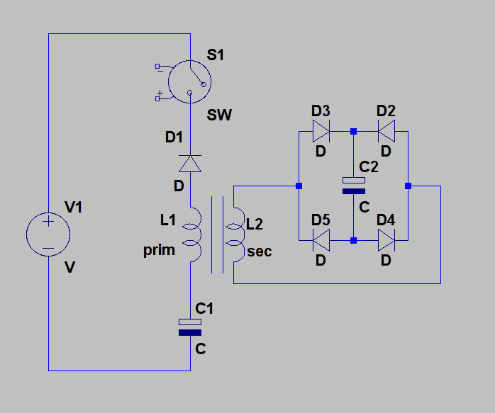
The capacitor acts in this place (in line with the coil) as a sort of failover safety device, ceasing any current in case of a switch failure - MOSFETs have a habit to die out shorting them self out, so a dead short appears in a circuit. With a capacitor in line with a switch, this leads merely a one shot pulse ending with the capacitor fully charged.
Hope I helped a bit?

Stevan C.Last edited by StevanC; 02-19-2011, 06:23 PM.Leave a comment:
-
What is the timing current/voltage impact of moving the Cap C1 between the switch and the transformer primary?
Why is this and improvement?
Where do we take the usable output from this circuit? Or, is this a single battery perpetual charger?
Hopes and Dreams.....
TjLast edited by tjnlsn255; 02-07-2011, 08:56 PM.Leave a comment:
-
Lamare,Originally posted by lamare View Post
I like your drawing, but here's how I would do it:
Put the diode across the switch, move the capacitor c1 to the positive side of the transformer, and add grounds to allow more current to flow easily.
Also, the transformer could be a relay with a secondary wrapped around it or a step up transformer made to work as a relay, to automatically open that switch when the core is saturated and the capacitor full! Or an additional relay could be added between the transformer and the battery negative to control the switch.
[ATTACH]7639[/ATTACH]Leave a comment:
-
The Next Generation Tesla Switch
Coming to a conference soon (hopefully) and hope to see you all there.
Hi gang, I haven't been doing a lot of posting here due to work load. Sorry.
Take a look;
YouTube - Tesla Switch Next Gen.mpg
I have been working on my new concept Tesla Switch. Still have a few issues to work out, but want to say a big thanks to John K. & Vissie for bouncing ideas off each other.
This device takes 4 batts, and like the swapper, targets the lowest batt. It then takes the 2 healthy batts and provides for a charging function to the selected batt. Once all batts are charged, it then will put a 24v @ 10amp load out. The logic will sense when the batts are discharge, then starts the process over again.
More to come.
Bit'sLast edited by Bit's-n-Bytes; 08-14-2011, 08:18 PM.Leave a comment:
-
Hi Matt!Originally posted by Matthew Jones View Post
Well as we speak, it's like I opened a can of worms: last night i devised a way to fit that tiny little stripeboard not less than 21 output lines each able to sink 350mA for a surge and all together totaling respectful 1A, the image is "about" to be posted and uses three ULN2003 chips.
I'm glad You like it, especialy woild be glad if anyone has a nerve/time to try (improve upon?) it out...
Best regards,
Stevan C.Last edited by StevanC; 01-29-2011, 12:25 PM.Leave a comment:
-
That looks really great Stevan.
Those Amtel boards are pretty neat as well.
Keep posting updates please.
MattLeave a comment:
-
While i gather materials, here few "peek over the shoulder" links for the (most) impatient:
https://sites.google.com/site/cest73.../jye-dso-0730x

Leave a comment:


Leave a comment: