Announcement

Collapse
No announcement yet.

Donald Smith Devices too good to be true

Collapse
X
 
  • Filter
  • Time
  • Show
Clear All
new posts

  • Resonance achieved, at least on the workbench....

    OK, back to the project at hand.

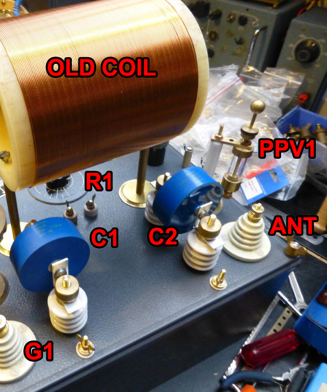
    Did I mention I was going to need more capacitance on the secondary? Try a LOT more capacitance. I disconnected the existing capacitors from the two terminal blocks across the L2 coil and measured L2 with my LC meter. It gave 2.7 uH, so I computed around 37 nF of capacitance to resonate at 500 KHz. I have some 10 nF film caps on hand, so I started attaching them across the two terminal blocks and measuring the resonant frequency with the function generator and scope as previously described. Apparently the true inductance of L2 wound this way is less than 2.7 uH, because it took 60 nF to bring the resonant frequency down to 511 KHz.

    Then I removed the function generator and powered up the ZVS, leaving the scope probe attached across L2. Tuning the C2 cap anywhere close to 500 KHz gives a similar scope trace on the screen, apparently L1 and L2 are coupled closer than critical coupling. They are definitely resonating together, as you can tell by the envelope on the scope trace. It takes about one full cycle to transfer most of the energy from L1 to L2 and then it rings down from the peak, although there is some sloshing back and forth of the energy between the two resonant circuits. This is basically exactly what you observe in a classical step-up Tesla coil, except that here the coupling is tighter than a typical Tesla coil. For those not as familiar with Tesla coils, google "first notch quench" and read the articles on some of the Tesla coil websites. This is a dual-resonant circuit very much like a classical "Tesla coil" except being used here in a step-down mode.
    Attached Files

    Comment


    • Was resonance achieved with the load connected? If not the response will be considerably different when connected. Just for the sake of thought a quick question... Is there a reason the secondary ( output ) circuit needs to be resonant to transfer power ?

      Comment


      • currently have about 4 related experiments going, one of which is the Don style spark to plate capacitor concept. It is illustrated here as "The simplest Free-Energy device (???)" about 1/3 of the way down the page. Vladimir Utkin's Free-Energy Secrets - March 2012

        The materials are easy enough to come by, has anyone else tried making one of these with any level of success? Using a 60 hz nst and a 6x12 plate capacitor I raised the temp of a heater strip 5 degrees just holding the spark off of the copper plate and following the diagram. still just getting started with this type of device, just like most of these other devices, I have half the necessary details to build an ideal working unit.

        my high frequency nst shuts off when I try to connect it that way. Need to try a high frequency spark gap and see the difference.
        Last edited by tesluh; 01-16-2017, 03:15 AM.

        Comment


        • Originally posted by dragon View Post
          Was resonance achieved with the load connected? If not the response will be considerably different when connected. Just for the sake of thought a quick question... Is there a reason the secondary ( output ) circuit needs to be resonant to transfer power ?
          No, there was no load on the secondary for this test. Obviously results will be different if there is a load, either a resistive load like the light bulbs, or the diode bridge driving the 12V supercap bank. The waveform I tested on the secondary is well over 100V peak-to-peak, so I expect this will get clipped off by the diodes if the bridge is connected.

          This actually brings up a very good point. One of my points of focus in understanding the Don Smith device and the phenomenon of "cold electricity" in general is, where exactly does the power gain manifest in the device? That is, if you test the voltage and current waveforms at every stage of the device, at some point magically this extra power appears. But what point it is it? Is it at more than one point? After much research and testing I believe I know the answer even though I have yet to prove it on the workbench. I believe that the extra power only manifests in the secondary of a transformer fed with radiant/scalar/cold electricity on the primary side. When all the conditions are properly met, then Lenz's law is reduced and the reflection of the secondary as seen in the primary side circuit is similarly reduced. To the secondary, it looks as if the primary side is being driven from a very low impedance even though it isn't, and to the primary it looks as if the secondary is at a much higher impedance than it really is. If this hypothesis is correct, then the resonance in the primary circuit will be much less affected by any load on the secondary. Hypothetically, the high voltage on C1 is acting to cause the antenna to draw in what Bruce calls "ions", which I think is somewhat of a misnomer. Whatever you call it, the result is that the energy C2 is charged with is not normal electricity but carries this extra characteristic. However, the power gain is only seen on the secondary side at L2, and only if the right things are happening on the primary side.

          Comment


          • I contend the secondary ( output ) coil does not need to be resonant, only the primary. Dealing only with the primary resonant circuit for adjusting peak output makes it much easier to deal with by reducing the overall variables.

            As an example, lets say you have a 50 turn primary and a 5 turn secondary. The energy on 5 turns of the primary is the same energy that is being transferred to 5 turns on the secondary. So, if you could tap 5 turns of the primary circuit, you have the same energy that is being transformed on the 5 turn secondary ( with less losses ). The only problem with tapping the primary is, generally the wire is smaller and wouldn't handle the current generated or would restrict the potential output. Also, no isolation between primary and secondary.

            Note in tesla's patents the transmitter primary has to be resonant with the secondary in order to maintain resonance - the receiver, however, has one coil resonant with the transmitter and the output is not a resonant circuit. Resistive loads or converting HF AC to DC, neither really care about the frequency. The only reason I can see to make the output resonant would be to convert the frequency to function with a proprietorial load - which could be done by converting to DC and driving an inverter or secondary circuit for that load. Bruce's circuit is basically the receiver.

            Personally I don't believe in "overunity", it's a term used to describe the fact that we don't understand where the energy is coming from - the gain in the system is a cause of an outside source. As we increase our understanding of this source, our circuits will reflect what we've learned. ( or haven't learned ).
            Last edited by dragon; 01-16-2017, 04:01 PM.

            Comment


            • Yes, I realized that in my pre-coffee morning state I forgot to address this point. I think you are correct, with perhaps one small qualifier. In my numerous bench experiments of Don Smith-style circuits I have tried both ways, with resonant caps on the secondary and without. You are correct that it doesn't seem to make a big difference as far as power transfer. I have measured the power throughput both ways and depending on the configuration sometimes the resonant caps seemed to help and other times didn't make much of a difference.

              The qualification has to do with my understanding of the nature of radiant energy and the phenomena at work in the Don Smith and all similar devices. The capacitor is universally seen as the receptor of this energy. Based in no small part upon my previous readings of this thread, I have come to understand that the voltage environment AROUND the capacitor matters. The voltage which would be attached to the case of the capacitor, if left at floating potential. You can easily take a capacitance meter and measure the terminal-to-case capacitance of a metal case motor run type cap, and it is on the order of 1000 to 1000000 times less than the terminal-to-terminal capacitance. The resonant caps on the secondary could be playing a part in receiving radiant energy, an effect which would be missing if they are not present.

              Comment


              • Primary done!

                Still waithing for a signal generator for tuning to resonance at 500khz...

                Comment


                • Some updates.

                  Moving the whole setup outside of the house. Got a lot of problems with usb hubs that do not work anymore when the system is on. A couple of weeks ago my motherboard died. Maybe that is the cause of the blown motherboard. So made a bench in the shed.

                  Looking for new grounding rods so i can try the two ground system. Any advice on this?
                  Got two grounds. But they are not that deep about 10 feet.

                  Last time the circuit ran i used a 110 watt light bulb. The filament lit a little but could not short it. So that needs some work.
                  The black wire on the primary is not enough anymore. With a screwdriver/ hand close 1 inch sparks would flyover from the windings.

                  At the higher voltages the primary will shake because of the frequency. You can feel and hear it. Like a iron core transformer sound.
                  Strange thing with the spark gap that there is cold air flow coming from it.A little cold breeze. What is that about? Cold electricity?

                  Need too insulate everything further because of the higher voltages. Not using anything metal anymore. Metal L-bracket for capacitor causing arc over between it.

                  So that is what i have been doing. Finished today with bench and rebuilding the system. Parts for the spark gap are coming. Polished aluminium sphere and steel tip. looking into good grounding system.

                  Comment


                  • The coil is on old coil just for demonstration.

                    The PPV Stage 2 housing can be seen on one side and the PPV Stage 2 anode and cathode materials are blurred on the other side.

                    One of the materials is common and the other is rare.

                    Too rare!

                    But can currently be bought from ebay across the world. It is not radioactive.

                    This could be synthesised but that's going to cost money so for now we might as well get the best out of aluminum and steel.

                    The PPV Stage 2 is twice as good as aluminum and steel can be.


                    This is an external portable unit to house super caps.


                    Last edited by soundiceuk; 01-17-2017, 12:15 AM.

                    Comment


                    • Taking a guess at the metal.

                      Tantalum?
                      Attached Files
                      Last edited by Mwtj; 01-17-2017, 12:19 PM.

                      Comment


                      • Someone found the nautilus... Captain Nemo is going to be a bit angry when he see's all that stuff missing !!! Nice work Bruce !

                        Comment


                        • The attached document is worth a read:
                          Attached Files

                          Comment


                          • Originally posted by dragon View Post
                            Someone found the nautilus... Captain Nemo is going to be a bit angry when he see's all that stuff missing !!! Nice work Bruce !
                            That isn't Bruce's build.....

                            You'll cry for joy when you see that!!!!!!!!

                            Comment


                            • Originally posted by Mwtj View Post
                              Is it the silver lining on the golden answer? Or is that too easy
                              Something lost in translation there?

                              Comment


                              • Originally posted by soundiceuk View Post
                                The attached document is worth a read:
                                REALLY interesting!!!
                                And it is an old document. He may have done great improvement since then...

                                Comment

                                Working...
                                X