 Tweet
Tweet
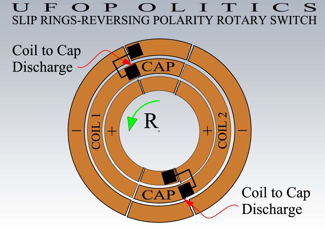
Coil reversal
Hi UFO
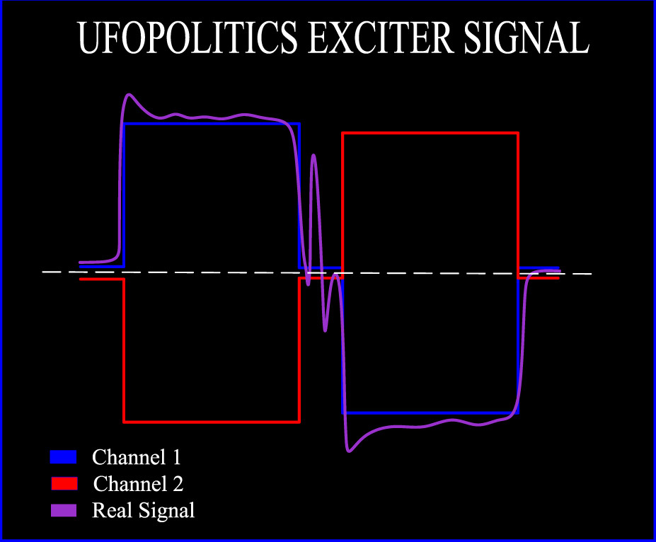
Your waveform however, shows a positive excursion followed by a rest at zero followed by a negative excursion this implies that one end of the coil is ground or zero volts.
Can you provide a new diagram that illustrates what you have said above?
L192
Hi UFO
Your waveform however, shows a positive excursion followed by a rest at zero followed by a negative excursion this implies that one end of the coil is ground or zero volts.
Can you provide a new diagram that illustrates what you have said above?
L192


Comment