This forum is preserved as a permanent archive. The community continues at eMedia Press.

Announcement

Collapse
No announcement yet.

My Motors got me to Tap into Radiant Energy

Collapse
X
 
  • Filter
  • Time
  • Show
Clear All
new posts

  • JohnStone
    replied
    Thanks for the hint. Unfortunately this driver is an older one and nither fast nore strong. The strong ones unforunately provide no current sense feature. But I choose a DIP8 pinning of industry standard so we can use differnet makes.
    JohnS

    Leave a comment:


  • JohnStone
    replied
    Clear answer: It depends
    1. Switch on/ off time: relates to the time of increasing / decreasing slope at output. This feature is essential.
    Do not estiamte we can get these values with poor drivers. We need optimized ones. The infineon coopMOS technology gets short switching time even at high amp and high voltage along low RDSon as well. It is an advanced technology and not expensive as well. I choose FETs above 50A / 600V and below 50ns switching time. These ingredients make up a very robust driver fitting for future applications as well.

    Please take in account that all sources of information state SHE likes to move herself at fast switching edges! So I recommend to not save some few bucks while making the driver 5..10 times slower. The magic performs while switching off with very steep edge. Imagine this to be a hammer out of steel hitting a nail compared to slow switching like adding to the same hammer a piece of rubber inbetween. She likes to be teased by sudden impacts.!

    2. Delay time: relates to the reaction time from operating the gate up to the FET decides to wake up in order to perform its task. This feature is essential if you intend to operate it at high frequency (> 50KHz) and / or extremely short pulses.

    Leave a comment:


  • Donald Haas
    replied
    Hi John Stone,

    Thanks more, valuable FET teaching.

    What do we want regarding "Typical Turn-Off Delay Time:"?

    Regards,

    bro d

    Leave a comment:


  • IndianaBoys
    replied
    Octopart.com is a quick search engine to locate electronic parts:


    IndianaBoys

    Leave a comment:


  • John Panettieri
    replied
    MC33153P (ON Semiconductor) - SINGLE IGBT GATE DRIVER

    Leave a comment:


  • JohnStone
    replied
    Coice of FETs

    Hi friends,
    in order to understand on why it is very dificult to suggest a certain FET:

    1. If we do not know what setup you have we do not know if you need 100A or 5A or any other value inbetween.

    2. Additionally we can not estimate the voltage spikes the FET will suffer in your setup. At lousy switching time you will get far less voltage spikes than fast ones.

    3. We do not know what funds you have available. (i.e. Cree makes superiour FETs starting at 47$ for one single FET)

    4. We do not know what sources you have available in your country.

    5. There are thousands of FETs of differnt makes available all over the world.

    In order to help you I entered at Farnell UK and serched for:
    • N-Channel
    • RDSon below 0.1 Ohm
    • Current more than 24A continuosly (at excellent cooling)
    • Voltage Vds more than 300V up to 1KV
    • Through hole packages (non SMD)
    1 2 3 from this output but you are encouraged to enter your data yourself in the Farnell search engine (prefer the local site in your country). Please be aware the choice list starts with negative values. Be sure to enter 300V max. and not -300V!!!

    Please make sure you specified roughly your setup and studied this list before you ask.
    JonS
    Last edited by JohnStone; 01-29-2013, 11:11 PM.

    Leave a comment:


  • IndianaBoys
    replied
    JohnStone,

    That is great!

    Here is a kit that simplifies creating PCB's (printed circuit boards) for those new to needing a way to do this:

    PCB Fab in a box:
    High Quality Single & Double-sided PCB's in 8 Minutes
    No Negatives, UV Exposures or Darkroom Chemicals
    PCB "Fab-In-A-Box" ... The 8min circuit board system

    Dealer Base
    PCB "Fab-In-A-Box" ... The 8min circuit board system
    DigiKey - Mouser
    Current Dealers
    Our dealer-base is growing in the USA and abroad. Internationally, our products are available in Canada, Australia, UK, Germany, India and Dubai, (UAE)

    IndianaBoys

    Leave a comment:


  • JohnStone
    replied
    Hi,
    all of you busy now. That's fine - me too. I prepare an easy to replicate instructable for monster dirver on bread board along easy to undestand templates for assembly and wiring as well.
    Breadboard approx. 3" by 3" including FET and holes for connecing high amp leads by screws. Excluding current sensor for now.
    Everybody can have the layout data for etching or milling own PCB.
    JohnS

    Leave a comment:


  • JohnStone
    replied
    Originally posted by prochiro View Post
    JohnStone
    I misprinted the last post to say (I have not mastered) when I wanted to say thanks, I HAVE mastered the opto. Sorry. I am digesting the rest of your post now.Dana
    OK. That's fine.
    As I understood you have running: opto, 74C14 drivers and FET directly attached to drivers? If you need more help please post a sketch of your circuit. (hand drawn and scanned will be OK)

    @ALL:
    I know my post yesterday is not easy to digest for non electronic trained guys. Big compliment to all of you who dare to get involved!!!! I will try to support!
    Therefore I will build the board myself along documenting the procedure. But I will add a LED for pulse check and a switch for disable driver and FET manually.

    Regarding current sense: I will prepare using it but please start without. It can be added later on.
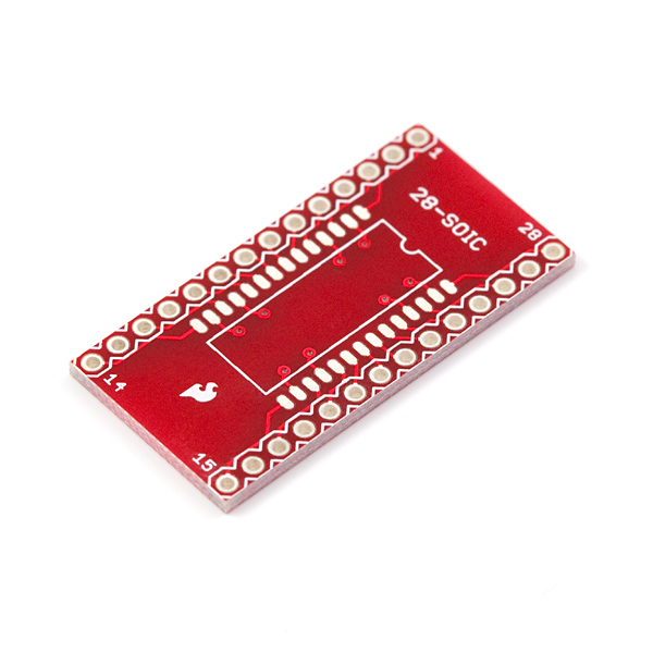
    For using SMD SO cases (i.e. ACS709) we can use this board below in order to make them usable for home brew setups.

    $3.95 at sparkfun
    JohnS

    Leave a comment:


  • prochiro
    replied
    JohnStone
    I misprinted the last post to say (I have not mastered) when I wanted to say thanks, I HAVE mastered the opto. Sorry. I am digesting the rest of your post now.Dana

    Leave a comment:


  • JohnStone
    replied
    Originally posted by prochiro View Post
    Hi JohnStone
    I not have mastered the SFH617A and all of its little needs etc. Have some schmitt triggers (74C14) but not (74hc14). It looks that on the surface you can use eather? Also what is the ucc27421, or is that simular to the acs714 for placement. Have you recieved and/or had time to check out the acs714 yet. I am excited but yet hopefully patient about building a monster pulser but as it looks so far it may not actually be that large in physical size except for the wire.
    Dana
    Hi Dana,
    sorry you still struggle! Are you sure your opto is still OK?
    I worked hard today in order to master my CAD program and now I have a new circuit diagram. The first part will be very similar for 555 driver and monster driver.

    At input connectror (left hand side) I have a resistor, the opto and the power /GND from generator separately connected. Thus we can adapt itmanually to specific generator outputs.

    I connected the opto from 5V to a resistor and from this junction to the first gate for signal conditioning (similar to schmitt triggerd drivers (74xx14). I realized we need a power on reset in order to prevent opening the driver at power on / off insolicited. Therefore I used those gates. The power on reset was built by R4 / D3 / C18.
    At power off the cap is discharged. It takes some time in order to be charged to a voltage enabling the gate attatched. This will happen if the power voltge is setteld well.
    At power off the diode in parallel to resistor will discharge the cap rapidly in oprder to be ready for next power on reset prcedure.

    The next gate performs as inverter and will forward a HIGH signal if the the opto is operated at input diode AND teh power on reset enables the first gate.
    You may replace the gates and power on reset by two inverters 74xx14 for test. 74c14 will function form 3V up to 16V but do not drive so powerful like 74HC14 being limited to 5V max.

    @All:
    I elaborated the layout for monster dirver in order to enable you all to build it easily. The components are through hole types and comply to 1/10" (2.54mm). Thus you can print it out and stick it on a bread board (holes with copper rim only / no copper stripes) In fact it took half a day to make it 1/10" compliant because I forgot to adjust the grid before.
    From one side you have the exact assemly template and from other side an exact wiring plan (one side wiring!)


    The artifact above is exactly what I will build on breadboard. I will have the components available soon (from Farnell or RS electronic) I will post my list along prices ASAP.

    But please note: it is still preliminary. I can approve it if I built it myself and tested it.

    Regarding driver:
    I decided initially for a component from TI UCC.... But except eBay I did not get any source. Once Cornboy suggested the Micrel make I got many sources. (RS / Farnell and others). So I decided for MIC4452. This driver is non inverting and there is a good reason I choose it. Inverting drivers (i.e. MIC4451) tend to oscillate quite easily and this (MIC4452) a non inverting driver, is much more reliable in different setups.
    The UCC.... drivers are pin compatible to MIC44xx. UCC... provide a disable signal additionall (pin3) but this pin can be left open for enable.

    Regarding Current measurement:
    Still pondering. There are several concerns:
    1. The simple sensors emit a small voltage as output. This needs to be amplified and valuated by a comparator. I do not trust in a home made setup to get it functioning safely - espacially in the noisy envirnonment if SHE is present.

    2. There are some types available with internal overcurrent comparator. But they are not available in through hole (SMD 16 pin and 24 pin housing only) Thus a regular PCB is required.

    3. I doubt if I can suggest a certain type for safe replication at all setups. The only viable solution for public is to buy those chips monted on PCB (see recent posts above) ACS709 and ACS714. And those who decide to do it on own responsibility because the signal needs to be amplified and valuated by a comparator - no chance for laymen. But I would be happy if anyone suggests a safe solution.

    In summary: please be patient, stay tuned and do not act hastily.
    JohnS
    Last edited by JohnStone; 01-27-2013, 11:03 PM.

    Leave a comment:


  • prochiro
    replied
    Hi JohnStone
    I have mastered the SFH617A and all of its little needs etc. Have some schmitt triggers (74C14) but not (74hc14). It looks that on the surface you can use eather? Also what is the ucc27421, or is that simular to the acs714 for placement. Have you recieved and/or had time to check out the acs714 yet. I am excited but yet hopefully patient about building a monster pulser but as it looks so far it may not actually be that large in physical size except for the wire.
    Dana
    Last edited by prochiro; 01-27-2013, 11:13 PM.

    Leave a comment:


  • JohnStone
    replied
    Target 3001 (freeware).

    @Lester: circuit diagram / PCB layout / 3D view / PCB production files / spice simulation included!

    I am not sure if this is the way to go. Maybe the second step only.
    But it might be a good template for all of you who will build such drivers on a bread board of this type.
    (no stripe board)
    You can imagine the placing of components and can use the PCB (both layers) as visual checklist for wiring. Apart that it is essential to perform the right wires as short as possible.

    The sample above is the monster driver but I am willing to forward the 555 driver as well if requested.

    My question is now: Will such a template help your replication?
    JohnS
    Last edited by JohnStone; 01-26-2013, 11:26 PM.

    Leave a comment:


  • Donald Haas
    replied
    BZW06-15 - MULTICOMP - DIODE, TVS, 15V, 600W | Newark

    BZW06-13 - MULTICOMP - DIODE, TVS, 13V, 600W | Newark

    Freight Charge: $20.00 once per order (two links above)

    BZW06-15B STMicroelectronics | 497-12462-1-ND | DigiKey

    BZW06-13B STMicroelectronics | 497-12759-1-ND | DigiKey
    Last edited by Donald Haas; 01-26-2013, 05:45 PM.

    Leave a comment:


  • JohnStone
    replied
    Originally posted by prochiro View Post
    Hi JohnStone
    Thanks for the help. Got it going now although it throws my frequency/duty cycle thinking for a loop as it is inverted from PWM.
    OK, got it. Here is a test circuit being not inverting.

    States:
    1. no curent at input -> transistor open -> 10K drags gate to GND -> FET off -> drain 12V -> bulb off
    2. current at input -> light at LED shining -> transistor switches on -> 1K drags gate to appr. 11V -> FET on -> drain GND -> bulb on

    But please note it is slow and thus not a final circuit for your pulser.
    Last edited by JohnStone; 01-26-2013, 10:39 AM.

    Leave a comment:

Working...
X