This forum is preserved as a permanent archive. The community continues at eMedia Press.

Announcement

Collapse
No announcement yet.

My Motors got me to Tap into Radiant Energy

Collapse
X
 
  • Filter
  • Time
  • Show
Clear All
new posts

  • sampojo
    replied
    Progress on ExpressPCB MD Design

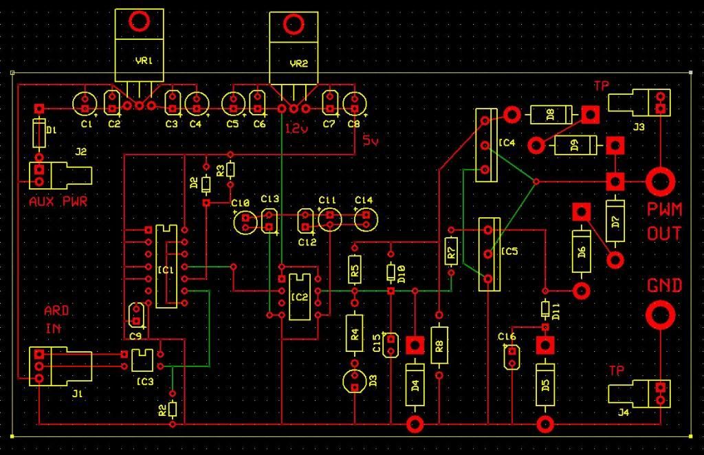
    OK some heavy wire traces figured out, cut out the empty space, got it down to about the size of JS board. Hopefully still a little more spread out, parts don't seem to close anywhere. I like the idea of separate boards, modularized. I envision a control box where the boards are stacked and could slide in and out when you get a failure.

    The costing is most is most sensitive to board size, and the next driver is the initial setup fee. So I got the board size down to under 10sq.in.

    I think JS recommended stranded 10ga wire where the heavy traces are, or filling the traces with thick solder as Dana has shown. These traces are .08 in. wide. I am getting confident enough in the layout to contemplate ordering...

    Red is board bottom, Green top.
    If anyone sees an issue pls. comment.
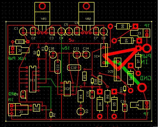


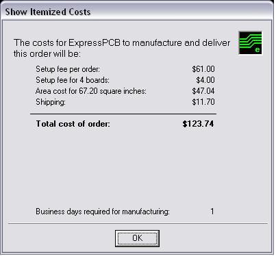
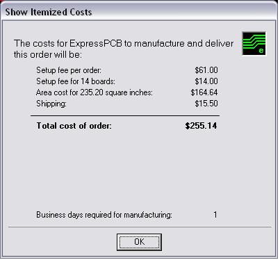
    Knocked 20% off the orders by size reduction.

    Leave a comment:


  • Cornboy 555
    replied
    Originally posted by sampojo View Post
    Hi Dana, thanks for the file, but what editor or tool opens it? AHA jpg!


    Hey Sampojo, if you go to Dropbox.com you can open a free account, and then just copy the file to your Dropbox.

    Regards Cornboy.

    Leave a comment:


  • sampojo
    replied
    What format is that file?

    Hi Dana, thanks for the file, but what editor or tool opens it? AHA jpg!
    Last edited by sampojo; 06-21-2013, 04:31 AM.

    Leave a comment:


  • prochiro
    replied
    @ Sampojo
    Here is a rough idea of circuit.


    Sorry for the curvy lines, my editor does not have a line tool.
    Dana

    Leave a comment:


  • sampojo
    replied
    check this logic about PWMs in general

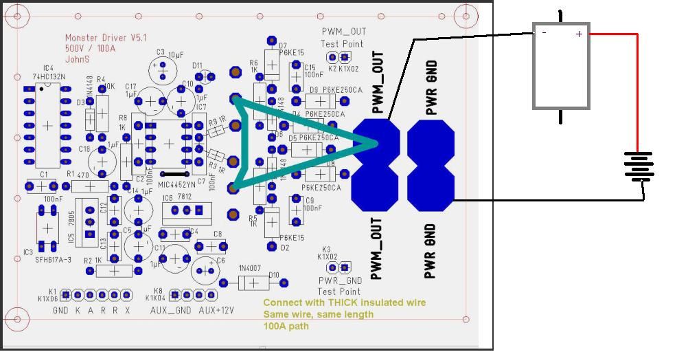
    Trying to get all those heavy wire connections JS shows in his material and wrote about. I was looking for the high voltage into the MOSFET, trying to understand how the gate might pulse the current and power. I am seeing the source pin go to ground and the drain going to PWM OUT. Wow, you'd think it'd be just the opposite! Pretty soon I am noticing no heavy power-in line being controlled by the MOSFETs or any power for the motor metered into the board at all. Then I remembered how a conventional PWM I have was hooked up. Although it has 2 separate positive voltage in lines, apparently one for power to the board and one for power to the motor, they were a shared common connection point on the board. However ground was a different story. It became apparent it conducted PWM by controlling ground access alone. Of course this must be the case for this PWM also. PWM OUT can be described best then as the MOTOR GROUND of a given brush set.

    So Dana, Kogs , another stupid question. Is this how you hook up a Monster Driiver board?


    AND Aux Pwr is just that a power supply separate from the batteries that run the motor preferrably but the ground between systems is shared?

    Kogs, thanx for the links to the parts!
    Last edited by sampojo; 06-20-2013, 04:18 AM.

    Leave a comment:


  • prochiro
    replied
    @ All
    Confusion will be solved here and all at one time.
    The JS post 3925 is the correct PDF for the Imperial. Sampojo post 1994 is also helpful. Over complication ideas about caps and resistors due to pictures and different description lines in parts list has many asking questions. All caps are electrolytic and the same small, cheap type, purchased in lots. So parts list line 9 is same as line 10. Resistors can all be of 1/4 Ohm, cheap. As for the resistor R2 on diagram, not needed as all boards are pulsed at independent lines. After building an exact PCB from page 15 in PDF, congestion of parts and lines make for difficulty when DIY boards are etched. This is at Opto area as well as around IC's. Small pads should be adjusted to larger and positioned so 10 gauge soldered stranded wire can be preformed and soldered in without overlapping. The circuit as shown up to the fet area could be purchased almost without change. There should be a two pin connector at each resistor leading to fets so separation on contact can be done for diagnosis. Another idea... as we will need four and as board cost is per piece and size, I think that you will find that putting four on one board would be cheaper in the long run. If you are not good at soldering in tight places with fine tips, maybe expansion will be necessary. Also the diodes which are marked as bipolar must be bipolar.
    Dana

    Leave a comment:


  • iankoglin
    replied
    Originally posted by sampojo View Post
    Hey gang, got the PCB done, tweaked the schematic with more data, got the bidir diode info in. Concerns: not using the large 100nf caps, couldn't find those kind yet. wire trace thickness, JS talked alot about thick wires.
    .
    G'day Sampojo
    I purchased mine here

    150 Pcs 500V 104pF 0 1uF 100nF 5mm Blue Ceramic Disc Capacitors | eBay
    It takes about 1 week
    Also Donald Haas I think told us to purchase the Infeon Cool mos Fets from Betty for $2 each Email her here [email protected] and tell her Donald Haas and Ian Koglin referred You she is a very obliging person

    They are genuine parts

    Kindest Regards Kogs

    Leave a comment:


  • iankoglin
    replied
    Originally posted by prochiro View Post
    @ Kogs
    JohnStone sent me his file some time ago but I need to find it in my computer. Here is what I can find at the moment, its a start.


    Dana
    G'day Dana , Donald Sampojo et, al
    I thought this forum had become defunct as my last post the last one on page 66 was the only page I could log into until now I must have tried to log into page 67 at least 50 times to see what was happening and was not able to that is until Today when Sampojo sent a reference to his post and I realised it was still alive I clicked onto his reference and was able to see his post. I then closed the page and again tried to load the forum once again but still page 66 was the last page I could access hence I posted the above post and now once again the forum is open to me and I can see there is a lot of reading to catch up on.
    Thanks guys for your input I am sorry I was not able to respond until now
    Kindest Regards

    Leave a comment:


  • iankoglin
    replied
    Originally posted by iankoglin View Post
    G'day Dana
    I like your monster driver setup circuit
    I have not been able to find any T3000 file of this circuit
    Please could you send me your T3000 file of it I would appreciate it
    I would like to make a copy
    I have purchased a "PCB Fab in a Box" it works great
    Kindest Regards

    Back at it again
    G'day Et, al
    I can not seem to view posts greater than my last one here
    So I am posting this to see If I can view any further
    Regards Kogs

    Leave a comment:


  • sampojo
    replied
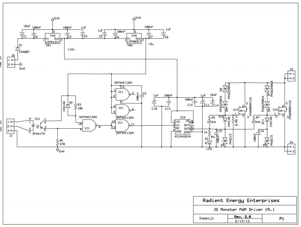
    ExpressPCB prelim layout done

    Hey gang, got the PCB done, tweaked the schematic with more data, got the bidir diode info in. Concerns: not using the large 100nf caps, couldn't find those kind yet. wire trace thickness, JS talked alot about thick wires.


    Board is 3x5.6in. It could be reduced some more yet.

    BOM

    Notice the pricing, price only doubles when quantity is more than tripled.


    Appreciate if any of you JS Monster Driver builders see any probs to let me know?

    Guess we need to build it to make sure it can work. Have the files, software. Click of a button to order. All automated. I will contact about the thread ordering in quantity, getting any other price breaks.
    Last edited by sampojo; 06-19-2013, 03:00 AM.

    Leave a comment:


  • Cornboy 555
    replied
    Thanks.

    Originally posted by sampojo View Post
    Been trying to fill in the blanks on the MD5.1 BOM as I been doing the schematic. The Express PCB tool is very simple, not sure how T3001 does things, optimizing layouts or some such, or whether JS did that using his knowledge. But still figuring out pad spacing/size and trying to understand the MOSFET layout and hook up parts there. I know John wants heavy short wire paths in critical areas I dont even know where exactly yet and that means a bit more work to come close to duping the T3001 layout. Sent ExpressPCB the schematic file with the T3001 gerber data and all of John's excellent diagrams and they say sorry, automation around their software only So the Stone layout seems to come in at 9 sq.in. under the 10sq.in. price break at ExPCB. Yeh!
    So get this thing laid out for this company and maybe get some volume business going! You can set up a BOM at companies like Mouser and Digikey, and they send you all the parts in one batch, no piece-mealing it. Then its like buying an electronic hobby kit and just need to assemble it.


    Thanks Sampojo, look forward to your progress.

    Warm Regards Cornboy.

    Leave a comment:


  • sampojo
    replied
    @cornboy on pc boards

    Been trying to fill in the blanks on the MD5.1 BOM as I been doing the schematic. The Express PCB tool is very simple, not sure how T3001 does things, optimizing layouts or some such, or whether JS did that using his knowledge. But still figuring out pad spacing/size and trying to understand the MOSFET layout and hook up parts there. I know John wants heavy short wire paths in critical areas I dont even know where exactly yet and that means a bit more work to come close to duping the T3001 layout. Sent ExpressPCB the schematic file with the T3001 gerber data and all of John's excellent diagrams and they say sorry, automation around their software only So the Stone layout seems to come in at 9 sq.in. under the 10sq.in. price break at ExPCB. Yeh!

    So get this thing laid out for this company and maybe get some volume business going! You can set up a BOM at companies like Mouser and Digikey, and they send you all the parts in one batch, no piece-mealing it. Then its like buying an electronic hobby kit and just need to assemble it.

    Leave a comment:


  • Cornboy 555
    replied
    9 monsters.

    Originally posted by sampojo View Post
    gravitating toward ExpressPCB.com, ~$100 for 4 circuit boards

    They want it in their own software format. Still trying to convert the T3001 files into their PCB tool, but checking to see if they will take the gerber data.

    here is the circuit pic in their tool: ExpressPCB MD5.1 schematic

    Here is the BOM


    Hello Sampojo, looks good, any chance you could get price on 9 of those for me as well?. Maybe i could deal seperately with the company using a part number, which ever way works best.

    Thanks a lot Cornboy.

    Leave a comment:


  • sampojo
    replied
    working to get the Monster drive PCB into production

    gravitating toward ExpressPCB.com, ~$100 for 4 circuit boards

    They want it in their own software format. Still trying to convert the T3001 files into their PCB tool, but checking to see if they will take the gerber data.

    Schematic correctected 6/15/13
    here is the circuit pic in their tool:

    Here is the BOM
    Last edited by sampojo; 10-10-2013, 02:34 AM. Reason: Corrections to data and diagram

    Leave a comment:


  • sampojo
    replied
    Resistors R3, R9; Capacitors C7, C8 ?

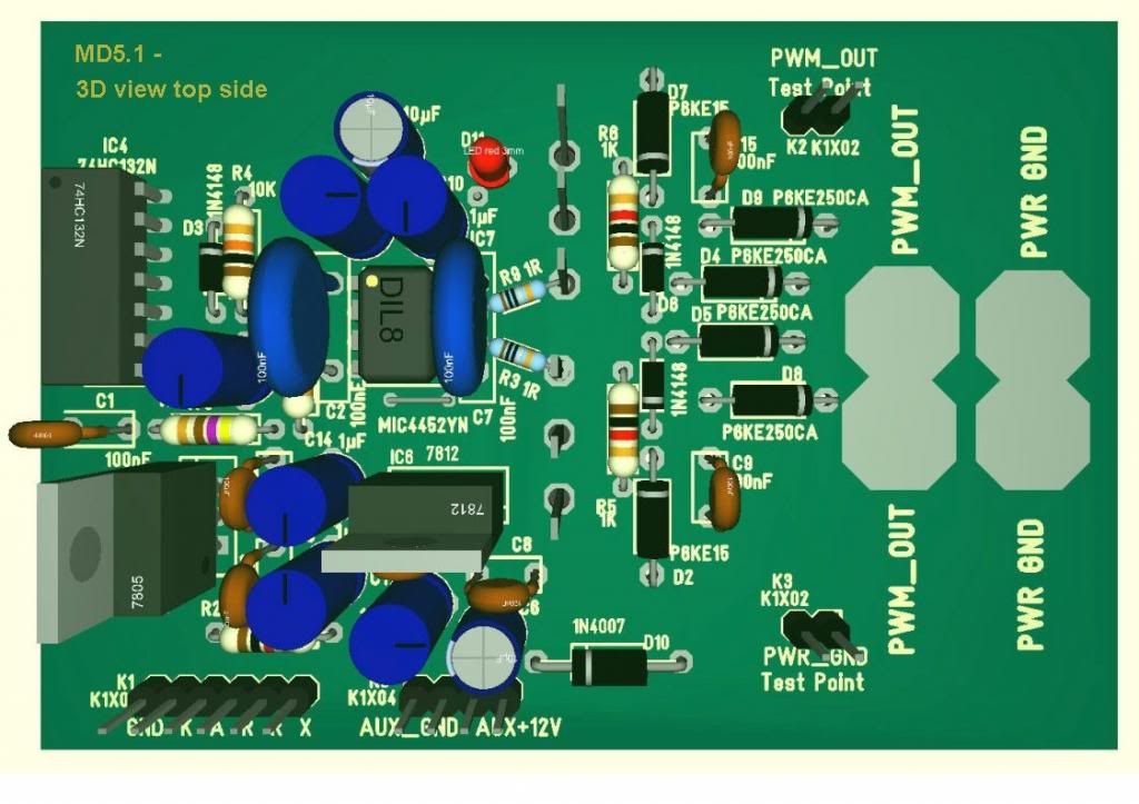
    OK looks like Resistors R3 & R9 are 1 ohm. In the center of this top view (obtained from MD5.1 - prerelease.pdf), you can read the resistors' color codes, 1 ohm.


    Now C7 and C8 are both 100nf but one is triple the size of the other and there are 2 of the big blue ones. There is nothing noted on the BOM about why the difference. I imagine it may be a voltage issue. Checking several parts distributors, I can't find anything like it.

    I have just spotted the BOM in the pre-release labelled pdf is newer and better than the one I was using. Word to the wise... See my previous post, it is on my dropbox...

    Looks like the non-electrolytic caps are tantalum?

    On these passive components, will the circuit be sensitive and not tolerate if I cannot find the exact form factors?

    On line 10 of the BOM:
    10 7 C1,C4,C8,C9,C12,C13,C15 100nF 6X3R5,08 pitch 5.08 mm / diameter 6mm / voltage > 20V
    1. For the bolded #'s, do they mean 6mm by 3mm, Radial casing for the "R"?
    2. Is pitch the lead spacing?


    Can I get some clarification? Dana? John Stone?
    Last edited by sampojo; 06-07-2013, 05:21 PM. Reason: add a question

    Leave a comment:

Working...
X