This forum is preserved as a permanent archive. The community continues at eMedia Press.

Announcement

Collapse
No announcement yet.

My Motors got me to Tap into Radiant Energy

Collapse
X
 
  • Filter
  • Time
  • Show
Clear All
new posts

  • sampojo
    replied
    Adding in the heavy wires on the MOSFETs

    looking at using 12 or 14ga solid house wires on the light blue connections here...
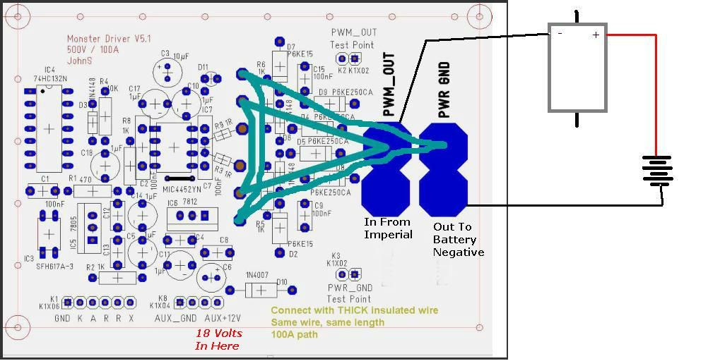


    I am supposing I should use 12 rather than 14, but I know it will take a lot more heat to solder, worrying about the components. Guess I can put some more heat sinking action on it like a small damp cloth...

    Would 12ga be enough for an Imperial style operation taking 12-18A?

    Leave a comment:


  • sampojo
    replied
    Heat sink ology

    Originally posted by Ufopolitics View Post
    Hello Sam,

    If the Heat Sink is supposed to be attached to Ground, and Ground goes to Battery Negative...Then you need to Isolate the Heat Sink from the Drain Contact through the Mica/Bakelite transparent sheets as also a washer/nut that is made of heat resistive plastic for the bolt/nut not to make contact with FET's Drain Plate...Only then you could use the Heat Grease based on White Silicon Compound which is not conductive electrically, only transfers heat.

    That is my opinion, however, I have to check again the Monster Driver Diagrams

    Regards Sam

    Ufopolitics
    hmm... So yeah the center pin goes to the drain and to the heat sink and to the negative on the motor, not battery ground. I guess grounding means grounding to battery ground and would be optimal. So mica insulators would be good. Got some pads from the salvaged heat sinks that must do just this job! only 2 though, good for only 1 board, but I at least know what to look for now.

    I am tempted to leave them floating and ungrounded but I bet that's a bad idea. Or even attached directly to Drain without an insulator. Again probably a bad idea. I wonder what Dana did?

    Leave a comment:


  • iankoglin
    replied
    Originally posted by Ufopolitics View Post
    Hello my Dear Friend Kogs,

    I believe the above statement tends to confusion...or am I wrong?

    The Drain of the MOSFET should go to the Negative Input of Motor, and Not to the Negative of Battery...am I right?

    Negative from Battery should go to Source of the FET.


    Kind Regards


    Ufopolitics
    G'day UFO
    You are Right The back of the Mosfets is also connected to the centre pin the Drain which when connected to the heat sink, and this is connected to the negative of the Motor


    Thanks for picking up my error I should proof read before pushing the submit button

    Thanks my friend

    Leave a comment:


  • iankoglin
    replied
    Originally posted by Ufopolitics View Post
    Hello Sam,

    If the Heat Sink is supposed to be attached to Ground, and Ground goes to Battery Negative...Then you need to Isolate the Heat Sink from the Drain Contact through the Mica/Bakelite transparent sheets as also a washer/nut that is made of heat resistive plastic for the bolt/nut not to make contact with FET's Drain Plate...Only then you could use the Heat Grease based on White Silicon Compound which is not conductive electrically, only transfers heat.

    That is my opinion, however, I have to check again the Monster Driver Diagrams

    Regards Sam

    Ufopolitics
    G'day UFO and Sampojo
    I corrected my post above

    The back of the Mosfets is also connected to the centre pin the Drain which when connected to the heat sink, and this is connected to the negative of the Motor

    Kindest Regards

    Kogs a bit

    Leave a comment:


  • iankoglin
    replied
    Originally posted by iankoglin View Post
    G'day Sampojo
    Bidirectional means just that you do not need to worry about polarity
    With regard to the diodes that are polarized you will notice that they have a stripe around the circumference one end and if they come taped together the tape on this leg is red colour this is the cathode end the striped end


    The back of the Mosfets is also connected to the centre pin the Drain which when connected to the heat sink, and this is connected to the negative of the Motor
    I hope this helps
    G'day UFO, Sampojo and all others
    I wrote the above in a hurry and did not proof read it
    UFO I am glad you noticed my error and I have corrected the above post

    So as to stop any confusion I will delete this Post in a few Days

    Kindest Regards

    Kogs has never ever made even one mistake Just 100's of errors and still going

    Leave a comment:


  • Ufopolitics
    replied
    If...

    Originally posted by sampojo View Post
    Kogs, thanks a million! so cool to have a show-stopper problem when you go to sleep at night and have blokes on the other side of the world answer the question for you when you wake up in the AM!

    Heres another worry wort problem, can't find my electronic heat conductive grease anywhere but would like to use it on the heat sink, but am concerned it may affect electronic conductivity on the ground connection of the heat sink. Better off grounding it independently then?
    Hello Sam,

    If the Heat Sink is supposed to be attached to Ground, and Ground goes to Battery Negative...Then you need to Isolate the Heat Sink from the Drain Contact through the Mica/Bakelite transparent sheets as also a washer/nut that is made of heat resistive plastic for the bolt/nut not to make contact with FET's Drain Plate...Only then you could use the Heat Grease based on White Silicon Compound which is not conductive electrically, only transfers heat.

    That is my opinion, however, I have to check again the Monster Driver Diagrams

    Regards Sam

    Ufopolitics

    Leave a comment:


  • Ufopolitics
    replied
    Drain To Negative of Battery?!

    Originally posted by iankoglin View Post

    The back of the Mosfets is also connected to the centre pin the Drain which when connected to the heat sink, and this is connected to the negative of the battery


    Hello my Dear Friend Kogs,

    I believe the above statement tends to confusion...or am I wrong?

    The Drain of the MOSFET should go to the Negative Input of Motor, and Not to the Negative of Battery...am I right?

    Negative from Battery should go to Source of the FET.


    Kind Regards


    Ufopolitics

    Leave a comment:


  • sampojo
    replied
    thanks Kogs! conductive grease anyone?

    Originally posted by iankoglin View Post
    G'day Sampojo
    Bidirectional means just that you do not need to worry about polarity
    With regard to the diodes that are polarized you will notice that they have a stripe around the circumference one end and if they come taped together the tape on this leg is red colour this is the cathode end the striped end


    The back of the Mosfets is also connected to the centre pin the Drain which when connected to the heat sink, and this is connected to the negative of the battery

    I hope this helps
    Kogs, thanks a million! so cool to have a show-stopper problem when you go to sleep at night and have blokes on the other side of the world answer the question for you when you wake up in the AM!

    Heres another worry wort problem, can't find my electronic heat conductive grease anywhere but would like to use it on the heat sink, but am concerned it may affect electronic conductivity on the ground connection of the heat sink. Better off grounding it independently then?
    Last edited by sampojo; 07-17-2014, 12:55 PM.

    Leave a comment:


  • iankoglin
    replied
    Originally posted by sampojo View Post
    My mouser part from Fairchild does not have a color band on the part to denote the cathode. The datasheet diagram says its supposed to. Can't just hook up a multimeter to see which way the current goes on these. Its says bidirectional. Does that mean it doesn't matter which way it goes?

    Any body know a way to tell which side is the cathode on these?

    RE post on MOSFETs, thanks cornboy! and thx! Very informative.
    G'day Sampojo
    Bidirectional means just that you do not need to worry about polarity
    With regard to the diodes that are polarized you will notice that they have a stripe around the circumference one end and if they come taped together the tape on this leg is red colour this is the cathode end the striped end


    The back of the Mosfets is also connected to the centre pin the Drain which when connected to the heat sink, and this is connected to the negative of the Motor
    I hope this helps
    Last edited by iankoglin; 07-17-2014, 11:38 PM. Reason: Correction

    Leave a comment:


  • sampojo
    replied
    Ground heatsinks for MOSFETs?

    Should the heats sinks for the MOSFETs on Monster driver be grounded to board ground?

    Leave a comment:


  • sampojo
    replied
    PKE250CA transil diode problem on Monster driver

    My mouser part from Fairchild does not have a color band on the part to denote the cathode. The datasheet diagram says its supposed to. Can't just hook up a multimeter to see which way the current goes on these. Its says bidirectional. Does that mean it doesn't matter which way it goes?

    Any body know a way to tell which side is the cathode on these?

    RE post on MOSFETs, thanks cornboy! and thx! Very informative.
    Last edited by sampojo; 07-16-2014, 09:53 PM.

    Leave a comment:


  • Cornboy 555
    replied
    Originally posted by sampojo View Post
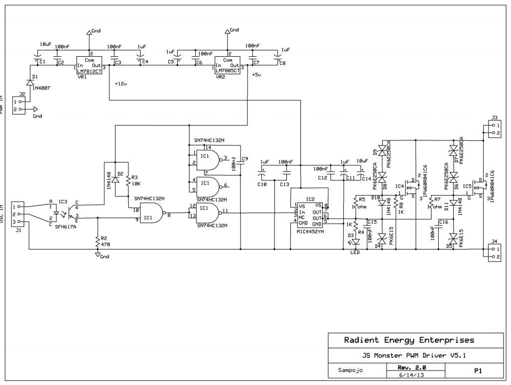
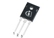
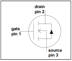
    Assembling my OSHpark Monser driver v5.1 boards finally. On the MOSFET, Pin 1 is the gate, Pin 2 the drain and Pin 3 the source. What I am seeing seems a little counter intuitive, is that the "source" pin is hooked up to the board and battery ground then? Is my understanding correct? Here are the diagrams.
    Schematic: (Note: R2 value is incorrect, has been changed to 330)


    Package diagram


    Piece schematic


    Using 1 ohm on R3,8

    Any input appreciated


    Hey Joey, that is correct, source to battery negative, drain to - end of motor coils.

    You are simply using these boards as an on/off switch on the low side, or negative side, completing the circuit.

    Great to see you building these now.

    Regards Friend, Cornboy.

    Leave a comment:


  • sampojo
    replied
    MOSFET question

    Assembling my OSHpark Monser driver v5.1 boards finally. On the MOSFET, Pin 1 is the gate, Pin 2 the drain and Pin 3 the source. What I am seeing seems a little counter intuitive, is that the "source" pin is hooked up to the board and battery ground then? Is my understanding correct? Here are the diagrams.
    Schematic: (Note: R2 value is incorrect, has been changed to 330)

    (This is now the corrected image, using blogspot instead of photobucket)


    Package diagram


    Piece schematic


    Using 1 ohm on R3,8 Edit: Sorry, threw up my old express PCB schematic, not numbered the same as JS T3001 schematic. It is R7,8 on this diagram and R3,9 on the JS schematic

    Any input appreciated
    Last edited by sampojo; 09-12-2019, 03:52 PM.

    Leave a comment:


  • Farmhand
    replied
    Yep I think you got it. Theoretically the basics are simple but getting
    it done with the results we want is not always so easy. There is always a "trade off".

    Cheers

    P.S. When we start talking of capacitors passing AC and not DC we get into an area where we kinda need to define "what is AC and what is DC".

    A capacitor will pass direct current but only until it is charged and it passes
    displacement current not "electron" current per se. Once the capacitor is
    charged if we discharge it we can charge it again with DC, in this situation
    the capacitor is being charged and discharged from a DC supply and we could
    hardly call it AC but the capacitor is being charged and discharged and in
    order to do that current must flow both ways, but it isn't what I would call
    "AC as such".

    If we take a capacitor and a battery and charge the capacitor then leave it
    like that, we have effectively caused the capacitor to pass some DC by
    displacement current. The statement that capacitor only pass AC and won't pass DC
    is a confusing statement and completely disregards the fact that we can charge a
    capacitor with a battery.

    A better way would be to say that a capacitor can only pass "displacement current".

    ..
    Last edited by Farmhand; 06-30-2014, 07:03 PM.

    Leave a comment:


  • Farmhand
    replied
    Originally posted by thx1138
    It seems I've blown a U7 MOSFET driver on my circuit board. Here is the source of my confusion from LN004 - PWM DRIVER for ASYMMETRIC MOTORS (V5.1) document:

    "R8 [typo S/B R3], R9 shall prevent spurious oscillations at FET side. They grow up along gate capacitance and inductivity of the leads between driver and FET. Therefore it is essential to have them as short as possible. The resistor values need to be determined at the setup itself. You are advised to check before with wire jumpers only."

    "You are advised to check before with wire jumpers only" needs a little explaining, I guess. I connected the wire jumpers between the output of the MOSFET driver (U7) and the gate of the MOSFETS. What that does is draw an almost infinite current, the resistance of the jumper being the only resistance. I was assuming the U7 MOSFET driver would handle the current limiting.

    I = V / R : Infinite = 12V / 0R
    It wouldn't be truly infinite because the wire would have some resistance and it would be limited by the amount the LM7812 and capacitors could supply but for an instant it would be everything they could deliver.

    Even with the 1 Ohm value for R3 and R9 given in the schematic it would be 12 amps.
    12I = 12V / 1R

    My understanding of MOSFET's is that they are voltage driven rather than current driven like BJT's. So it seems they don't need nor do we want much current. Is that correct?

    I'm guessing I should have used the "jumper wires" to test different resistor values and they shouldn't have been connected directly from the driver output to the MOSFET gate.

    As I said in my earlier post, this is my first power handling circuit. Could someone please tell me the resistances they are using for R3 & R9 and how they came up with the value?
    Hi thx1138, Basically the gate of a mosfet is a capacitor, with "N" channel parts,
    when the capacitor (gate) is charged to the "turn on" voltage (typically 10 volts) the mosfet is "on",
    and when the capacitor (gate) is fully discharged the mosfet is "off". To switch
    the mosfet on and off fast requires a fairly high peak current both ways "on" and "off".

    Because it's a capacitor it won't allow any continuous direct current to pass once the gate (capacitor) is charged.
    The more the current to the gate is restricted the slower the capacitor (gate) will charge
    and also cause the mosfet to turn on slower, which in turn causes a longer
    amount of time that the mosfet is transitioning through it's resistance range before
    it achieves it's full lowest "on" resistance. A TO220 mosfet can have typically
    a up to several nF of capacitance to the gate. This capacitance needs to be
    charged and discharged to from 0 to over 10 volts and back to zero as fast as
    is practical in order to reduce transition resistance losses in the mosfet as
    a result of the main current from drain to source heating of the mosfet itself,
    due to current through a resistance while the mosfet is conducting but not yet fully "on".

    A resistor between the driver and the gate will serve to restrict the current
    charging the gate capacitance if it is necessary, and can damp unwanted
    oscillations at the gate, but reducing the gate drive current too much is detrimental.

    The charging and discharging of the mosfet gate is a "switching" loss.

    Here's a PDF from microchip about it.

    Driving Power MOSFETs


    ..

    P.S. For example, I encountered a particular problem when trying to drive an IRF740
    at over 1 mHz with a TC4420 mosfet driver chip, the driver chip heated up
    because
    it was charging and discharging the mosfet's gate capacitance 1 million times each second,
    which meant it had to pass a considerable peak current for a good portion of each second.
    The mosfet itself stayed cool but the driver chip got very warm because it was working hard.

    ..
    Last edited by Farmhand; 06-27-2014, 09:36 PM.

    Leave a comment:

Working...
X