
thx1138
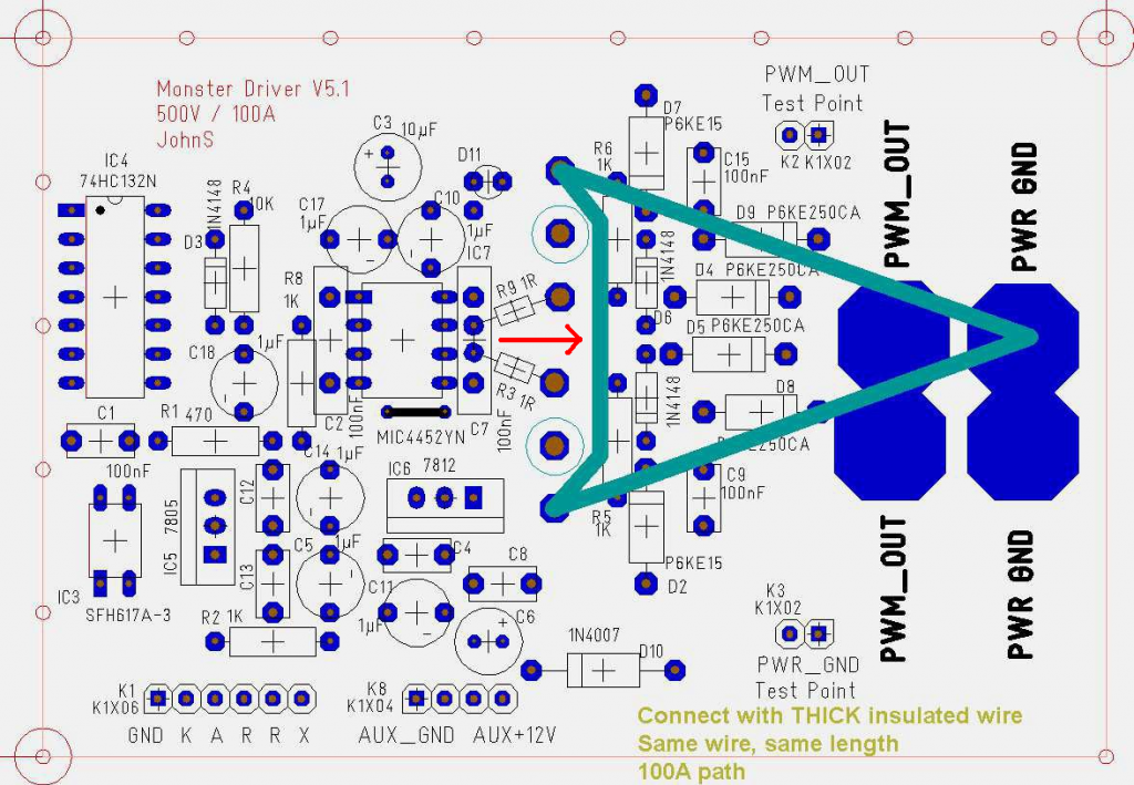
The cross wires you see there and are talking about are part of a triangle make of at least 10 gauge wire and soldered thru. John stated in file LN1004 that the cross wire MUST be inserted as shown so as to even out the feed to bolt sides. Any patch on the board will not show a failure when testing but will cause failure when amps come across. I strongly advise to stop any alteration of this circuit and make it exactly as in file LN1004. I have made many of these in groups of four and eight. This file shows how to make it correctly without fail at high amps. I also see dirty boards shown that have a film and chunks of solder splashed everywhere. This is the best way to ruin your day when you run your motor and get an arch of amps across the board. You guys are talking as if you have not read file LN1004. Maybe a reread is in order. You can not out design Johns work and second guesses will lead to second set of boards needed in the long run.
Dana
-
G'day Dana, Sampojo and rest of the teamOriginally posted by iankoglin View Post
Today I made a lift to lift the rear wheel off the ground then I rebuilt the blown JS Monster and fitted it direct to the motor on my bike I by passed everything I had there so the only load applied was the motor turning the rear wheel as soon as I applied current the JS Monster blew or I thought they had as they seemed to have latched on the motor was going full bore I took the Mosfets out and checked them they were OK I checked the other major chips everything was ok but the LED would not light so I checked the PMW oscillator it worked BUT the Driver would not work I placed the Mosfets on another board and checked it was OK it was so I again connected in the bike and the same thing happened Fets OK the major components OK but No LED on.
I used a 6 Fet Controller the same as I used on my CLF Bulb circuit I connected it up exactly the same as previous It runs OK at start up the motor draws just about 29 amps then drops back to 2 amps.
I was a bit Game I locked the wheel with my hand so that the motor was not able to turn it I kept it fixed in that position for say 30seconds when when I released the wheel it sped up I felt the Fets heatsink,and motor they were still cold
So my observation is that the JS Monster does not like the initial surge
I think tomorrow that I will connect everything back as it was using the 6 Fets controller with the exception to the relays and the Caps If OK then I will try connecting the caps along with a DPDT toggle to firstly Isolate the caps from the battery when switched of and secondly to connect the Batteries and the caps before starting the motor that way the caps take the initial load from the battery then start the motor.
If that goes well I will take it for a drive BUT not to visit Cornboy
@ Sampojo
It looks like you have the 12v auxiliary positive and negative connections reversed. The pins are soldered underneath double. The pins From the right the first 2 pins are 12v>15v max the next 2 left are Negative a space then the next 2 are the Oscillator in then miss 2 the extreme left 2 are also negative
Please Sam What connectors have you fitted
Kindest Regards

Kogs getting a bit of headwayLeave a comment:
-
Completed second MD5.1 OP board
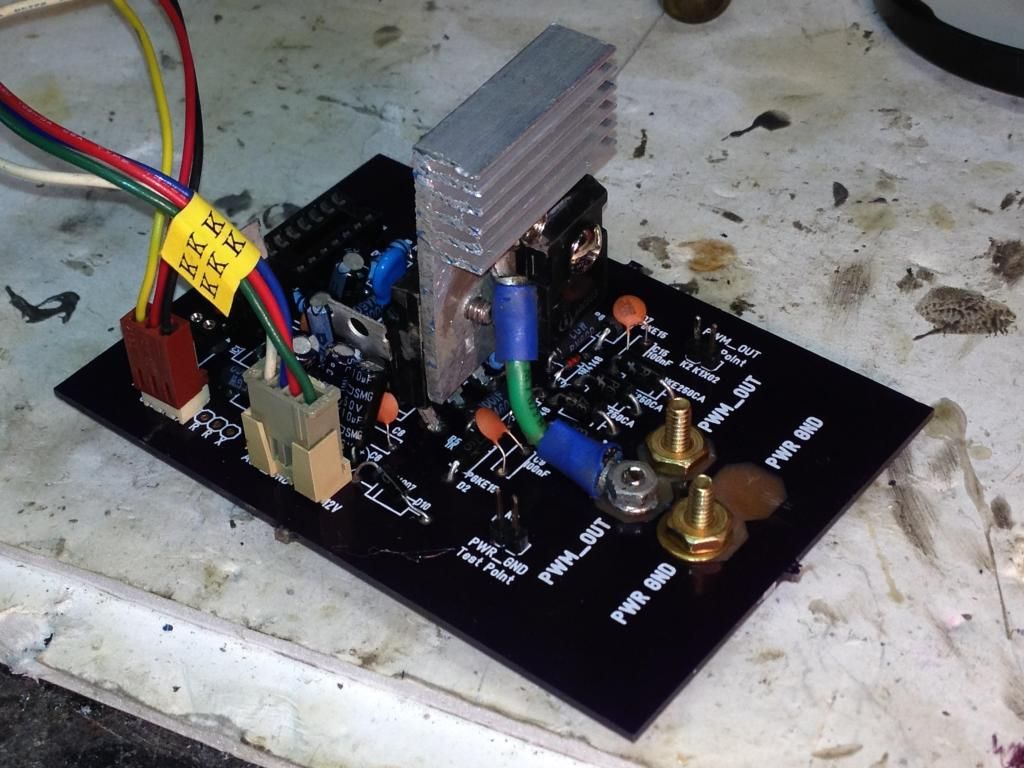
Now have enough to drive a dual stator at least. This one uses the heatsink as part of the circuit, as Kogs suggested.
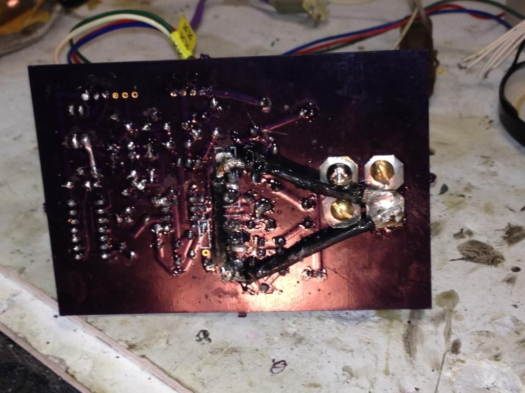
board bottom:
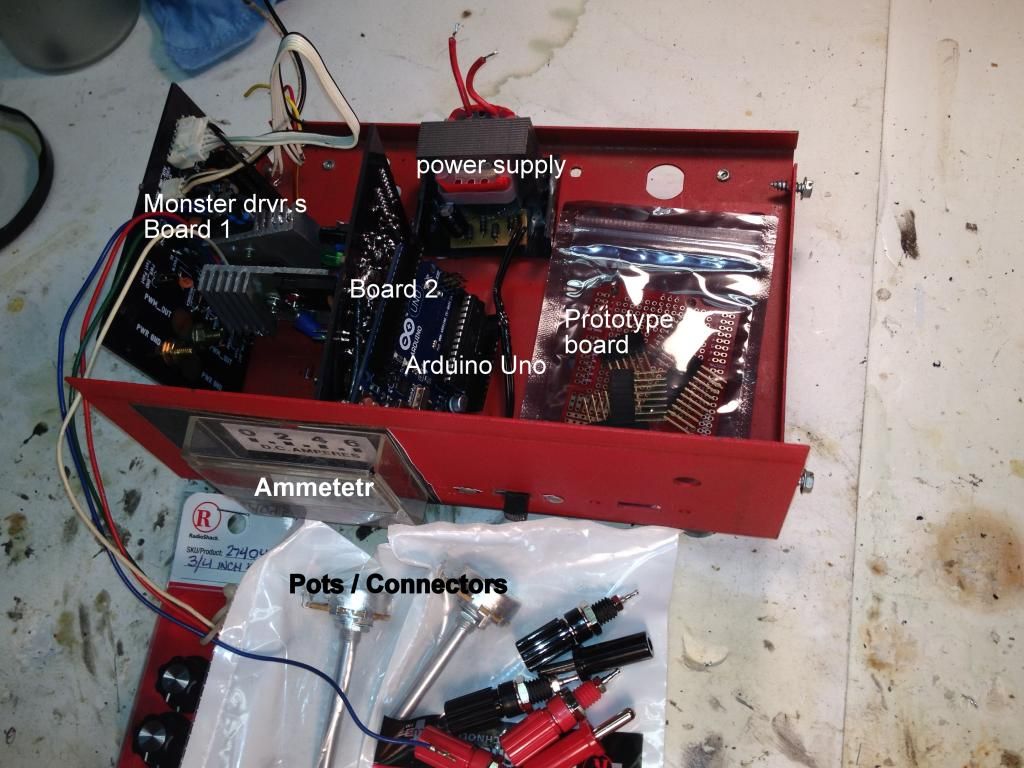
Building a Asym Motor Controller, first for Dual Stator, will expand for a Quad. Salvaged an old battery charger box. It will take either DC or AC power. The Arduino ports will come out the front, as will the Monster driver connection posts. Intend to have the ammeter be selectable for each channel. I would need some sort of rotary switch. The charger original isn't very accurate but can give you an idea. Expect to replace it eventually with a more accurate gauge that can measure 20 amps at least.
Leave a comment:
-
G'day DanaOriginally posted by prochiro View Post
I fitted a JS's Monster with 4 Mosfets I put it in the circuit as it was yesterday put the bike on its side to take the load off the wheel when I tried to start nothing happened.
I then by passed the monster and connected the Motor direct to 36v battery no load it drew 20.5amps then dropped down to 2 Amps
Tomorrow I will be checking every bit of the circuit bit by bit until I find where the problem Is perhaps the relays are damaged I will find out tomorrow
I definitely need to sort this out
I appreciate your input
Kindest Regards
Kogs getting Frustrated a bitLeave a comment:
-
Hey Kogs, on reflection, your blown fets the way you describe them as rubble, smacks of amperage overload not voltage.
Caps are notorious for dumping high amps instantly, so I do believe you need to look at how that could happen in your system.
Don't want to have to come and pick you up, half way to my place.
Regards Friend, Cornboy.
Leave a comment:
-
Speaking for John Stone...
Almost jumped on this idea too, thx, but I think John S. would say you lose some support between the two FETs if you drop out these bridge connections (red arrow)? I vaguely recollect the discussion...Originally posted by thx1138
Leave a comment:
-
Heat sink and paste call & arduino hook up question
THX: Right on about the reason for the open circuit on the heat sink, did not sand before application! Applied paste as described, no detectable resistance. I am going the Kogs route on this board and use the heatsink as the drain connection and save one of those heavy duty soldering sessions and extra stress on the Mosfets...Originally posted by thx1138 post2826
Still unclear on how to hook up the arduino to the monster driver.
Do I use the Opto A or Opto K pin (and GND)?
Simple matter of trial and error I suppose, but would like to get it right the first time. Here is the schematic.
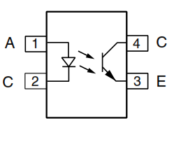
EDIT: C pin on the left is the K pin that John has used perhaps from a European manufacturer
And what is the other pin for then? An inverted input signal perhaps? Looks like A pin is standard input signal?
TIALast edited by sampojo; 07-30-2014, 12:47 PM.Leave a comment:
-
Blown Fets
Kogs
Putting double fets in each spot cuts stress on each one in half. John did say that on larger motors that this would be necessary. In any case, I feel it is just good backup coverage. Those fets blew way to fast. The mathematical calculations and the real life needs often are not the same.
DanaLeave a comment:
-
caps
Kogs
These different types act in different ways. Sounds like waiting for the new super-caps might be helpful.The Caps I used on the bench for testing are super caps but the ones in my Bike are Electrolytic ones
In my mind, the super-caps are a means to redirect energy. Might it not be wist to just use the system without caps to proof the first part of system. In other words, isolate motor function first.
Also, a question. When you were just pedaling the bike, was there any possible electrical connection from your motor/generator/caps that may have been able to function as its counterpart and cause incorrect electrical balance? Don't know if I asked this correctly but hope you know what I mean. If it did, then when starting system, unbalance could have blown like lightning.
DanaLeave a comment:
-
G'day CornboyOriginally posted by Cornboy 555 View Post
Thanks for your input I understand what you are saying
I also have been thinking about the same thing I used them earlier when I was replicating Bedini's energisers I even have a YouTube here
https://www.youtube.com/watch?v=KE1yYc1InTk
https://www.youtube.com/watch?v=Z7fWj8AWb74
The Neons last for some time and they eventually break down
I spent 2 Years trying to get this Machine going Bedini said that these machines sold by Rick Friedrich were an exact replication of his 10 coiler
And that is why I bought one But that was not true they had neo Magnets for a start Rick said that for the price they would come with a mechanism that would allow you to adjust the coil gaps of all the coils at the same time of course they did arrive without this attachment he said that he was not supplying them because they were going to cost him $600.00
But What I do not understand is that when I tested these motors/ controllers I stalled the motor on more than one time with different motors and each time I did not have a problem with the controller it drew more amps got a bit hotter but never blew any Mosfets
I would tomorrow try some neon's they would by pass 90v to ground BUT am reluctant to because I am sure this is not the remedy as if this is not rectified that means that the neon's will keep protecting the Mosfets until they break down and then I would be stuck (probably somewhere back of Burke) that probable would happen When I trip up on Nessie to visit you
The Mosfets that were first in the Bike when I disassembled the circuit the Source pins were Rubble fried right off.
When I first used Super capacitors about a month ago I connected them in parallel with the battery that had in the circuit a voltage regulator I just can't remember what the circuit exactly was but when I switched on the battery the regulator fried and I am sure that was because the caps were empty about 1v and they instantly drew the power from the battery and or anywhere they could to reach capacity.
Its a bit different when they are charged they can be regulated in their discharge but when it comes to charge them they want to drain everything around them
Kindest
Regards

Kogs dilemmaLeave a comment:
-
Hey Kogs, don't know if it will help, but try placing 3 small 90v neon's in series across the drain and source, to physically monitor the back flow, if they are flashing, you are heading for a crashing!!!.
Regards Cornboy,
PS. Tasmania,!!!! BRRRRRRRRR.
Leave a comment:
-
Kogs EBike update
G'day PembeltonOriginally posted by Pembelton View Post
I have not assembled the Mosfets in the wrong the way John Stone made the circuit Board is so that the gates are in the centre and the Source pins are towards the outside The drain pins are in the middle of both he used a heavy cables to connect the drain to the power out and the Source to the ground to me it was a problem to solder these heavy cables after the components were installed so I decided to use 12G high current cables and solder into the circuit board before the components, JS also made it so that the Mosfets were on the underside of the board I chose to make the board just a bit larger between the low current and high current portions so I could mount them on the top also so I could fit double Mosfets in parallel if required. these are the Boards I am showing/using here.
I also have Modded J Stone's circuit by re arranging things so that the Mosfets are assembled both the same way to make it easier to mount heat
sinks But these I am not using here.
@ Dana and all
I disassembled the 4 Mosfets in the board I just Blew it was just the Mosfets.
I have just replaced the 2 Mosfets to the first board I just have blown the Source pins were totally disintegrated. I re connected this board to the same circuit except I disconnected the Capacitors It works just Fine. This proves to me that the caps are the problem, BUT HOW am I going to overcome this Problem
The Caps I used on the bench for testing are super caps but the ones in my Bike are Electrolytic ones
Kindest Regards
Kogs working overtimeLeave a comment:
-
G'day PembeltonOriginally posted by Pembelton View Post
Thanks for your input
I have been using these JS Monster drivers also the drivers that UFO showed us 2 Years ago, for some time now and have never had this problem it seems now I am using a Cap bank I have this problem.
I think you are right the only problem with that is we are collecting the energy produced by the Motor and directing this back to the battery via the caps
Kindest Regards
http://i1193.photobucket.com/albums/...9x89_57418.gif
Kogs Photo Bucket does not work againLeave a comment:
-
G'day DanaOriginally posted by prochiro View Post
I had already a JS Monster with double Mosfets I used it sometime ago on various testing it worked I did not see any real difference I was told by several persons that only one Mosfet should be enough to drive a 250w motor so I continued making them with just the 2 Mosfets as JS designed it
it is to cater for 200v 100a I realise that it needed finer tuning with the 1 ohm resistors.
That being said I connected it up to my motor and it worked OK I then connected to it up to the circuit that I was using for Nessie and as soon as I started the motor it blew the Mosfets at least that is what I imagine as I have not pulled it down to test it yet.
I notice that the LED adjusts to the PWM as I turn the pot but the motor is not effected it just goes full bore So I am sure it is the Mosfets.
I am now convinced that it is some how connected to the Capacitors.
I have though connected them in parallel to the battery with the Diodes just as UFO has stated in Nessie's circuit
It may be that the caps draw from the battery in the first instant and probably it may draw through the controller
Perhaps I need another diode to redirect the current from the battery
I really need to sort this out before I start putting Nessie's works together
I have purchased 50 pcs 2.7v 500F super capacitors and they should be arriving sometime within the week.
I will be experimenting with them they will make 2 banks 13.5v 500F each I was going to put these in series to give me 27v bank I could run with a 24v system
If it is the caps that are the problem and when I have them sorted I will be a happy chappie.
I have to get going and replace the Mosfets and get Sorted
My wife says I need to get all these things sorted as she wants to sell the house and move to Tasmania.
Kindest Regards
Kogs slowly getting thereLeave a comment:

Leave a comment: