This forum is preserved as a permanent archive. The community continues at eMedia Press.

Announcement

Collapse
No announcement yet.

The Golden Tractate of Hermes Trismegistus applied to electromagnetism

Collapse
X
 
  • Filter
  • Time
  • Show
Clear All
new posts

  • kEhYo77
    replied
    Originally posted by Dave45 View Post
    Is this to collect through the antenna
    Could you give more detail, explain your idea.
    Thanks
    dave
    It is to be used as a few turn primary for a Tesla Coil (transformer).
    Having seen Primer Fields on YT, it is my belief that this PHI ratio clockwise / counter clockwise / clockwise type of primary winding will by very efficient.

    @MonsieurM

    I purchased recently some 99.9 pure Bismuth and the plan is to make a thick primary from copper pipes with ferrofluid inside and cover it with a thin layer of Bismuth from the outside.
    And the final (Bismuth covering) layer should be of an insulating material.
    Last edited by kEhYo77; 02-13-2013, 12:39 PM.

    Leave a comment:


  • MonsieurM
    replied
    Originally posted by kEhYo77 View Post
    Hi.

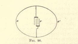
    What do you think about this schematic?

    If the breakdown avalanche effect of the diode is big enough we could have some interesting results

    kEhYo
    good reading you kEhYo77

    first a reminder of what is the breakdown avalanche effect

    Avalanche breakdown
    From Wikipedia, the free encyclopedia
    Jump to: navigation, search

    Avalanche breakdown is a phenomenon that can occur in both insulating and semiconducting materials. It is a form of electric current multiplication that can allow very large currents within materials which are otherwise good insulators. It is a type of electron avalanche. The avalanche process occurs when the carriers in the transition region are accelerated by the electric field to energies sufficient to free electron-hole pairs via collisions with bound electrons.
    [edit]
    Explanation

    Materials conduct electricity if they contain mobile charge carriers. There are two types of charge carrier in a semiconductor: free electrons and electron holes. A fixed electron in a reverse-biased diode may break free due to its thermal energy, creating an electron-hole pair. If there is a voltage gradient in the semiconductor, the electron will move towards the positive voltage while the hole will "move" towards the negative voltage. Most of the time, the electron and hole will just move to opposite ends of the crystal and stop. Under the right circumstances, however, (i.e. when the voltage is high enough) the free electron may move fast enough to knock other electrons free, creating more free-electron-hole pairs (i.e. more charge carriers), increasing the current. Fast-"moving" holes may also result in more electron-hole pairs being formed. In a fraction of a nanosecond, the whole crystal begins to conduct.

    Avalanche breakdown usually destroys regular diodes, but avalanche diodes are designed to break down this way at low voltages and can survive the reverse current.

    The voltage at which the breakdown occurs is called the breakdown voltage. There is a hysteresis effect; once avalanche breakdown has occurred, the material will continue to conduct if the voltage across it drops below the breakdown voltage. This is different from a Zener diode, which will stop conducting once the reverse voltage drops below the breakdown voltage.

    When both sides of the pn junction (called a depletion layer) which is lightly doped become large enough avalanche breakdown takes place.
    indeed it could prove to have some very interesting effect ....

    just on a side note : as we have discussed several times the use of Bismuth in free energy devices ( Hall effect Battery , Moe Joe Cell etc .... ) :

    Bismuth-Ferrite Piezoelectric Material Opens New Roads for Energy Generation - The Green Optimistic

    Leave a comment:


  • Dave45
    replied
    Originally posted by kEhYo77 View Post
    Hi.

    What do you think about this schematic?

    If the breakdown avalanche effect of the diode is big enough we could have some interesting results

    kEhYo
    Is this to collect through the antenna
    Could you give more detail, explain your idea.
    Thanks
    dave

    Leave a comment:


  • kEhYo77
    replied
    I finnaly get it!

    Hi.

    What do you think about this schematic?

    If the breakdown avalanche effect of the diode is big enough we could have some interesting results

    kEhYo
    Attached Files
    Last edited by kEhYo77; 02-13-2013, 10:22 AM.

    Leave a comment:


  • MonsieurM
    replied
    Wireless power transfer technology for high capacity transit

    The Korea Advanced Institute of Science and Technology (KAIST) and the Korea Railroad Research Institute (KRRI) have developed a wireless power transfer technology that can be applied to high capacity transportation systems such as railways, harbor freight, and airport transportation and logistics. The technology supplies 60 kHz and 180 kW of power remotely to transport vehicles at a stable, constant rate.

    Read more at:


    where did read this before :


    Leave a comment:


  • MonsieurM
    replied
    from: http://www.energeticforum.com/renewa...ations-18.html


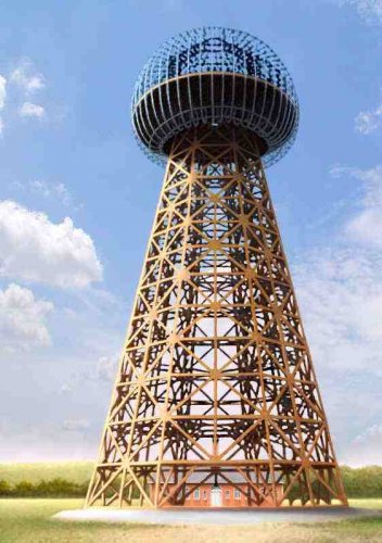
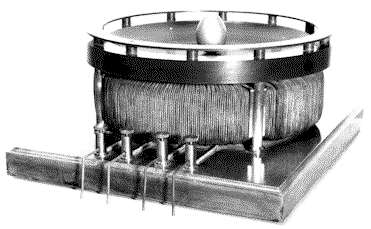
    the shape of the coil looks almost "egg like" https://www.youtube.com/watch?featur...&v=NJ7saXwMYUU


    also considered a favorable aerodynamic shape

    +

    The inventions, researches and writings of Nikola Tesla, with special reference to his work in polyphase currents and high potential lighting

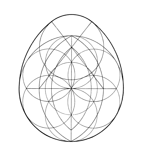
    on a side note ..... you can print the above image and place pegs to create an egg like coil ( basket weave or not )


    Last edited by MonsieurM; 02-06-2013, 10:32 PM.

    Leave a comment:


  • MonsieurM
    replied


    a fractal construct has an 'efficient function', it has a fractal ergonomy to them, they function on multiple levels and in multiple dimensions:
    New 'retention model' explains enigmatic ribbon at edge of solar system

    (Phys.org) It emits no light and no conventional telescope can see it. However, particles from inside the solar system bounce off this boundary and neutral atoms from that collision stream inward. Those particles can be observed by instruments on NASA's Interstellar Boundary Explorer (IBEX). Since those atoms act as fingerprints for the boundary from which they came, IBEX can map that boundary in a way never before done. In 2009, IBEX saw something in that map that no one could explain: a vast ribbon dancing across this boundary that produced many more energetic neutral atoms than the surrounding areas.

    Read more at:
    In a paper published in the Astrophysical Journal, researchers propose a "retention theory" that for the first time explains the key observation of the unexplained ribbon's width. The paper appeared online on Feb. 4, 2013. Indeed, since the discovery of the ribbon, over a dozen competing theories seeking to explain the phenomenon have been put forth. The new theory builds on one that was first published along with the discovery of the ribbon in 2009 and then quantitatively simulated in 2010. This theory posited that the ribbon exists in a special location where neutral hydrogen atoms from the solar wind cross the local galactic magnetic field. Neutral atoms are not affected by magnetic fields, but when their electrons get stripped away they become charged ions and begin to gyrate rapidly around magnetic field lines. This process frequently aims ions back toward the sun. So those ions that pick up electrons at the right time might explain the extra boost of neutral atoms that create the ribbon. The problems were that physical processes might break down the distribution needed for it to work and that models based on this process showed a ribbon narrower than IBEX observed.

    Read more at:
    The new theory adds a key process: That rapid rotation creates waves or vibrations in the magnetic field, and the charged ions then become physically trapped in a region by these waves, which in turn would amplify the ion density and produce the broader ribbon seen. Read more at


    Last edited by MonsieurM; 02-06-2013, 02:51 PM.

    Leave a comment:


  • MonsieurM
    replied
    thank you Dave

    could also explain some of the UFO sightings viewed from Space : Plasma filament behaving in peculiar manner

    Leave a comment:


  • Dave45
    replied
    Giant veil of “cold plasma” discovered high above Earth | The Extinction Protocol: 2012 and beyond

    Leave a comment:


  • MonsieurM
    replied
    Fibonacci quasicrystal - Wikipedia, the free encyclopedia

    A Fibonacci crystal or quasicrystal is a model used to study systems with aperiodic structure. Both names are acceptable as a 'Fibonacci crystal' denotes a quasicrystal and a 'Fibonacci' quasicrystal is a specific type of quasicrystal. Fibonacci 'chains' or 'lattices' are other synonyms used with regard to the dimensionality of the model.[1] While it is used mostly as a theoretical construct, physical models are also implemented for empirical checks. Most of its applications pertain to various areas of solid state physics.
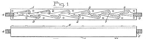
    Quasicrystal - Wikipedia, the free encyclopedia


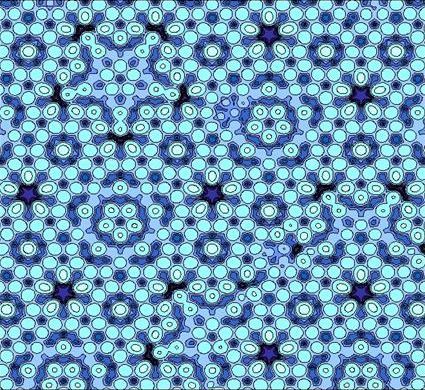
    Two-dimensional aperiodic tiling based on the Fibonnacci word

    The mathematical properties of the Fibonacci word and related topics are well researched and readily applied in such studies. The elements of a Fibonacci crystal structure are arranged in one or more spatial dimensions according to the sequence given by the Fibonacci word. The Fourier transform of such arrangements consists of discrete values, which is the defining property for crystals. In an algebric form the sequence is expressed with a matrix whose eigenvalues are Pisot numbers. This feature guarantees that its Fourier transform is discrete. Material waves with appropriate length would interfere constructively when interacting with a Fibonacci structured physical system. For instance, when submitted to X-rays, a Fibonacci quasicrystal would produce Bragg peaks. Other features describing media behaviour such as damping, transmitivity, etc. can be evidenced on Fibonacci models.[2]

    The Fibonacci-based constructions are an obvious example of quasicrystals that do not possess a 'forbidden symmetry'. Their diffraction pattern would be of a square type with the intensities arranged in a fractal pattern.[3]
    +


    CCC Sacred Geometry Page 2


    +

    from :


    Originally posted by MonsieurM View Post


    Various patterns of standing waves on fluid surfaces generated by vibrating the containing vessels with various driving frequencies, producing A: hexagonal, B: rectangular lattice, C: quasi-crystal patterns, among many more. D: This pattern is defined more by the shape of the walls of the container rather than by the driving waveform, showing how interference patterns in the resonating system tend to subdivide the resonating system into periodic and symmetric sub-patterns in an essentially Gestalt manner.
    Harmonic Resonance Theory: An Alternative to the "Neuron Doctrine" Paradigm of Neurocomputation to Address Gestalt Properties of Perception

    Harmonic Resonance Theory
    note picture C


    ready .......


    Evolution inspires more efficient solar cell design: Geometric pattern maximizes time light is trapped in solar cell

    new design for organic solar cells that could lead to more efficient, less expensive solar powerthe researchers sought to design the geometric pattern of the scattering layer to maximize the amount of time light remained trapped within the cell.

    Read more at:
    -----------------------------

    6 Harmonic Resonance Theory

    The properties of perception as observed phenomenally and as described by Gestalt theory are truly baffling when it comes to proposing a computational mechanism to account for those properties. However there is one physical phenomenon that exhibits exactly those baffling properties observed in perception, and that is the phenomenon of harmonic resonance, or the representation of spatial structure expressed as patterns of standing waves in a resonating system (Lehar 2003a, Lehar 2003c). This tantalizing similarity cannot be coincidental, considering that no other physical mechanism or phenomenon has ever been identified that exhibits these same enigmatic properties. The most remarkable property of harmonic resonance is the sheer number of different unique patterns that can be obtained in even the simplest resonating system. A pioneering study of more complex standing wave patterns was presented by Chladni (1787) who demonstrated the resonant patterns produced by a vibrating steel plate. The technique introduced by Chladni was to sprinkle sand on top of the plate, and then to set the plate into vibration by bowing with a violin bow. The vibration of the plate causes the sand to dance about randomly except at the nodes of vibration where the sand accumulates, thereby revealing the spatial pattern of nodes. This technique was refined by Waller (1961) using a piece of dry ice pressed against the plate, where the escaping gas due to the sublimation of the ice sets the plate into resonance, resulting in a high pitched squeal as the plate vibrates. Figure 1 (adapted from Waller 1961 P. 69) shows some of the patterns that can be obtained by vibrating a square steel plate clamped at its midpoint. The lines in the figure represent the patterns of nodes obtained by vibration at various harmonic modes of the plate, each node forming the boundary between portions of the plate moving in opposite directions, i.e. during the first half-cycle, alternate segments deflect upwards while neighboring segments deflect downwards, and these motions reverse during the second half-cycle of the oscillation. The different patterns seen in Figure 1 can be obtained by touching the plate at a selected point while bowing at the periphery of the plate, which forms a node of oscillation at the damped location, as well as at the clamped center point of the plate. The plate emits an acoustical tone when bowed in this manner, and each of the patterns shown in figure 1 corresponds to a unique temporal frequency, or musical pitch, the lowest tones being produced by the patterns with fewer large segments shown at the upper-left of figure 1, while higher tones are produced by the higher harmonics depicted towards the lower right in the figure. The higher harmonics represent higher energies of vibration, and are achieved by damping closer to the central clamp point, as well as by more vigorous bowing. There are many more possible patterns in a square plate than those depicted in figure 1, which would be revealed by suspending the plate without clamping, allowing patterns which do not happen to exhibit a node at the center of the square, and of course there are many more patterns possible in plates of different shapes (Waller 1961), and many more still in volumetric resonant systems such as a vibrating cube or sphere, which define three-dimensional subdivisions of the resonating volume, although these have not received much attention due to the difficulty in observing the standing wave patterns within a solid volume or volumetric resonant cavity. Faraday (1831) extended Chladni's phenomenon by observing standing waves on the surface of liquids, which produces geometrical arrays of standing waves on the surface of the fluid in the form of concentric rings, parallel ridges, grid and checkerboard patterns, arrays of cone-like points, and even brick patterns. This work has been extended more recently by Cristiansen et al (1992), Kumar & Bajaj (1995), Kudrolli & Gollub (1996), Kudrolli et al. (1998) and others, who have demonstrated patterns of equilateral triangles, regular hexagons, superlattice, and quasi-crystal array patterns by driving the oscillation of the fluid layer with a controlled waveform. Figure 2 shows some of the patterns produced by Kudrolli et al. It seems that this work is only touching the surface of the full potential of this phenomenon for producing complex geometrical patterns by relatively simple driving oscillations.
    Last edited by MonsieurM; 02-05-2013, 04:18 PM.

    Leave a comment:


  • MonsieurM
    replied
    Originally posted by StweenyA View Post
    Wow!!! Just trying to keep up here...
    StweenyA ........ welcome back ...... good reading you again


    an old version of the previous posts


    Leave a comment:


  • StweenyA
    replied
    Wow!!! Just trying to keep up here...

    Leave a comment:


  • MonsieurM
    replied


    Electromagnetic spinning top - Inception inspired toy - YouTube

    This is my newest steampunk toy - an electromagnetic spinning top . Inside the brass top there is a small neodymium magnet which interacts with the coil hidden inside the wooden box . The circuit detects the position of the magnet and generates the magnetic pulse when the magnet is aligned correctly . The device is able keep the top spinning for over ten hours using four AA batteries.
    --------------- an interesting discussion took place about the set up :

    How did you get the top to stay in the center? All of my attempts end with the top retrograding and scribing a circle on my glass or moving in a triangle pattern. I have also tried an induction design (Tesla's Columbus' Egg), but I don't have powerful enough electromagnets for that. I would be VERY appreciative of any and all more information that you could give me.
    I found that the problem with stability is caused by too strong magnetic field produced by the electromagnet. The repulsive force caused by it is the source of the precession because its vector always points away from the centre . Using the massive top to increase the inertia and setting the current in the coil to the point at which the rotation is maintained but the precession is minimal seems to work the best. .
    Spinning Magnet - Sixty Symbols - YouTube


    Last edited by MonsieurM; 02-04-2013, 09:32 PM.

    Leave a comment:


  • MonsieurM
    replied
    funky mama soul beats - YouTube + Soul Know How To Make Music(70's Funk) - YouTube
    are you ready for some good funk

    for those who are already trained at Mental Projections : don't be

    ps: Tesla .... you Sly Dog


    +

    inside the egg :


    +

    on top of


    +

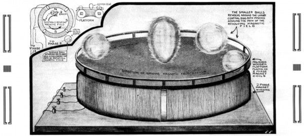
    Tesla Patent 787,412 - Art of Transmitting Electrical Energy through the Natural Mediums


    ever wondered why the balls around the eggs are spinning ... they are not in the vortex within the concave Bump


    Last edited by MonsieurM; 02-03-2013, 02:50 AM.

    Leave a comment:


  • MonsieurM
    replied
    from: http://www.energeticforum.com/renewa...tml#post223674

    Originally posted by Gazzasore
    Cheers Maybe if I do a Mark 11 ill use this idea cheers

    This guy does a similar thing https://www.youtube.com/watch?v=bjcm...FBEDE63E5478EC
    Gaz
    https://www.youtube.com/watch?v=e7nFga2BpGU ..... you won't have to go into high rpm as in the vid

    or more like this one :

    Tesla turbine powered by water - YouTube


    side note : All of Tesla's work is scalable ..... all you need is

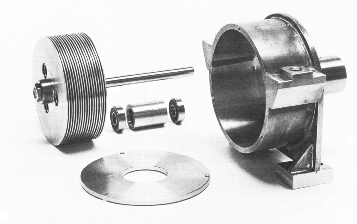
    copper tube / fittings for the casing ..... and some small magnet rings .... and you can do the same .... with some retooling ..... thought worth to mention

    Copper and water are diamagnetic so it repels a moving magnet.


    ----------------------------------------


    if you prefer the other way magnetizing your water ...... interestingly also included as a part of the Tesla Turbine :

    I 'd like to bring your attention to the principle used in the Valvular tube ..... Nikola Tesla: Disk Turbine / Pump (Articles, patents, links)


    some parts need to be replaced by magnets ...... try to guess which


    -----------------------------

    "Before I put a sketch on paper, the whole idea is worked out mentally. In my mind I change the construction, make improvements, and even operate the device. Without ever having drawn a sketch I can give the measurements of all parts to workmen, and when completed all these parts will fit, just as certainly as though I had made the actual drawings. It is immaterial to me whether I run my machine in my mind or test it in my shop. The inventions I have conceived in this way have always worked. In thirty years there has not been a single exception. My first electric motor, the vacuum wireless light, my turbine engine and many other devices have all been developed in exactly this way." N. Tesla

    see also :


    Magnetic Gear - YouTube + Magnomatics - Magnetic Gear - YouTube

    Uploaded on Dec 31, 2010

    The objective of studying magnetic gears is to replace mechanical gears which are noisy, require frequent maintenance and lubrication, and suffer from friction losses. The magnetic gear is contactless and quiet in operation, and it requires no lubrication. In addition, it slips when overloaded whereas the mechanical gear may break down when overloaded.
    The magnetic gear has been studied more thoroughly in the last decade although there was a patent in 1901 by Armstrong(1) and an improved one in 1941 by Faus(2). Another significant improvement was contributed by Martin in 1968(3) in which steel pole pieces were used. However, it was not commercially marketed because the transmitted torques were small as ceramic magnets were used. Recently, strong rare earth magnets have been developed, and the new operational principle employing the harmonic magnetic flux has also been developed. As a result, a high torque density can be achieved. Hence, high performance magnetic gears can be marketed for industrial and commercial applications.
    The theory of mgnetic gearing was established by Dr. Atallah and his colleagues at Sheffield University.
    Friction Gear


    Last edited by MonsieurM; 02-02-2013, 08:42 PM.

    Leave a comment:

Working...
X