
Originally posted by petar113507
View Post
-
A very interesting experiment, there is an electric field orbiting there somewhere, if I had to guess Id say its orbiting inside and outside the glass container notice one metal conductor is placed inside the glass and one outside when shorted the two electric fields combine to give the spark. -
Im trying to get ahold of BruceTPU on the other forum he's done alot of work on the TPU.
Maybe get some more insight
Leave a comment:
-
Yepp.
I probably had it wrong.
Ed's PMH is basically doing this, but with the magnetic component -- not the electric... The electric field is independent of the magnetic component in terms of when they are generated in the PMH -- but each can influence the other...
MIT Physics Demo -- Dissectible Capacitor - YouTube
(I wasn't thinking much about this one. I did not want you to think for me. Will do refresher on leedskalinin's experiments.
 )
)
Sleep time soon,
==RomoLeave a comment:
-
You could be right Peter testing would be the best answer, if you started off with a low voltage more could always be added later.Originally posted by petar113507 View Post
But I think the basic idea is sound, Steven said he was taking advantage of the small kick that was present and I think that kick he was talking about was caused by the electric field that was present because of the pmh.
Normally there is no kick in a normal circuit but because of a preexisting field caused by the pmh setup there is
Leave a comment:
-
High voltage with many turns on the first coil? Everything I can remember tells me high voltage doesn't produce strong magnetic fields.Originally posted by Dave45 View Post
I don't know if high electric tension would make a stronger/better E field.
Maybe it doesn't matter, because you're separating the two components anyways...
Do you think the E field's strength outside the PMH solely deals with the voltage in the coils in the PMH?
I always thought the permanent magnet's magnetic strength was determined by how strong a magnetic field it was subjected to in the first place. I implicitly figured the N/S magnets traveling in/around the iron in the PMH worked the same way.
My disclaimer here -- I could be thinking incorrectly because I'm focused on the magnets, not the E field. I haven't played with it yet either -- I'm just guessing right now. You've brought up some excellent things to test. 
Will be testing soon.
==RomoLeave a comment:
-
Here's an article that states that the company that Steven was working for was not able to patent the whole design because part of the design was in the public domain for years (Eds PMH).
but with the new patent law im sure they have ran it through.
I think they know free energy is coming thats why they changed the patent laws so it will be illegal to have a free energy device in your home.
When the people finally realize this there will be a revolution in this country, its coming and it wont be pretty.Leave a comment:
-
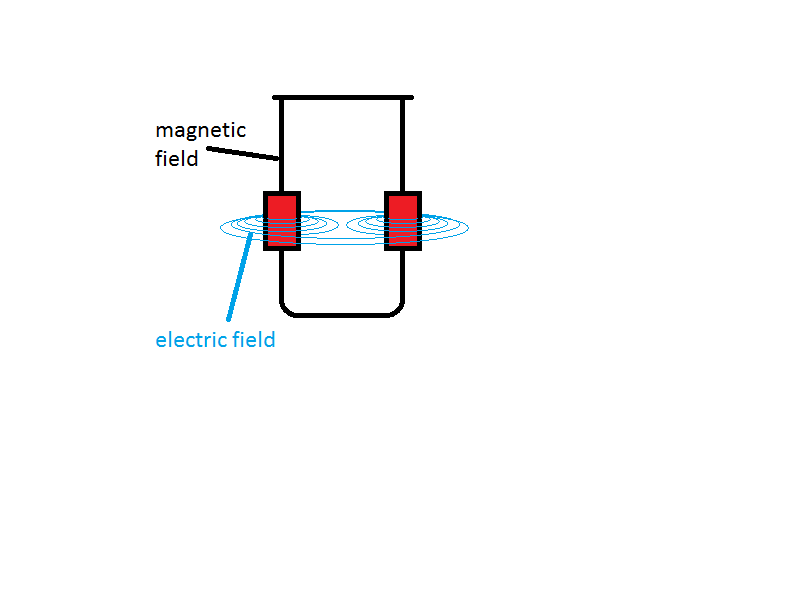
The electric field has two directions just like the magnetic field and I think in a toroid they run inside and outside like in this model.
Leave a comment:
-
Then again we may need to use the same toroid with four sets of windings two to use as the pmh and two to collect.
We need a soft iron core just as Ed used in the pmh
Leave a comment:
-

If we use one toroid like the pmh we should be able to oscillate a small voltage through the other toroids windings and collect the electric field from the first toroid.
If the first toroid had a high voltage put in it will create a large magnetic and electric field and will run perpetual like the pmh,
then by oscillateing a small voltage through the other toroids windings we should be able to collect the first field with a circuit that is designed to collect bemf.Leave a comment:
-
Hey PeterOriginally posted by petar113507 View Post
Your right about the vid, a very good demonstration of the two electric fields being attracted to each other. Your seeing it now look at other devices and see whats happening, Im also going to build the pmh, a free perpetual electric field to play with.
I think the TPU was a modified PMH,Leave a comment:
-
My bad on the late reply here MM. I've been real busy with "people things".Originally posted by MonsieurM View Post
My father came up to visit me over this last week.
I talked with him a bit, and had some good personal insights about where I come from. It's nice to talk with someone who is older than you and has a more "broad" perspective on some subjects. Makes it so It's not so black and white sometimes.
That aside, I'm swamped with a research paper and "excersize homework" for my "education responsibillities" of Econ and Business accounting
I've had to put the building part on hold for a little bit, and get caught up first. I tried to wind two different rodin coils around cardboard, and miscalculated the length/winds because I figured it was okay to "guesstimate". Same mistake both times...
The second time I thought "Well, I'm in a hurry -- there's no way I can make the same mistake"
Not repeating that one again. There's a reason tesla called it an "art". Winding good, clean coils is kinda like a sculpture purposeful beyond personal expression. Bought a "Rock-a-stax" to imitate the Alex petty Rodin coil for the plastic doughnut rings, and am going to calculate the lengths/wraps this time. Still haven't bought a heat gun to make my own coil moulds -- but it's on the to do list.
Still freezing different sizes of smith coils -- testing different metals for "ground sinks" for the ice. Zinc plated Steel seems to work alright -- everything focuses down to the nail tip. If I'm not careful about the placement of it in the ice, I can still get some discharge cracks.
Aluminum screen sinks the field out pretty well. I think there's a better metal to be used -- am still testing. It's weird to see the ice be clear-ish, and not opaque because of the discharge/structured column. If you don't ground out the screen with another battery cathode, or into a pot of dirt -- the metal doesn't ground out the E-field entirely.
Also, collidal silver froze, and worked as a slight conductor. Less discharge cracks than the control "null" group. Haven't tried spinning the collidal silver yet.
Collidal silver (or I'd imagine copper would work too) works best when frozen on top of a thin bottom layer of ice -- otherwise the silver bits settle down on the bottom sometimes. Leaves a nice shiny powder -- I'd rather that powder be suspended in the ice though.
When my dad was up here, he left the collidal silver generator with me -- so I've got a steady supply now.
I'm planning out a few projects which are very multi-purposed. I'll use the following things for several purposes. Mostly because I've spent a little while cracking apart disposable cameras and shocking myself. One way or another and I think I've figured out how the circuit works.
Among the most interesting things about disposable cameras --
(You can get a ton of them for free if you ask nicely )
-I've found the voltage trigger in the flash tube to make some townsend discharges.
If you charge the "big cap" on the disposable camera (the one that makes the high pitched ascending squeak from the primary transformer) slightly enough to not discharge its current through the tube when you ionize it; you can hit the "trigger" for the ionization plate behind the discharge tube, and see the tube slightly glow.
Also, I've figured out how I can get some kilovolt voltage out of the little transformers.
High voltage bottle capacitors
Hook those "Bottle caps" to a Marx generator design. The step-up voltage action from the Marx Generator, is really just a clever charge/discharge of the capacitors from parallel/series. Should be able to charge up those capacitors
Marx generator - Wikipedia, the free encyclopedia
If I play this one right -- might not even be so difficult for the resistors. Water Resistors
Currently Making plans to make a PMH to play with the electric field. Hoping to get my HHO torch tip soon, so I can melt my own glass torrid shapes/dielectric materials for capacitors.
Thought I'd share an experiment I'm going to try as soon as I get a free moment.
Crudely drawn for the moment.

Top left corner, I have illustrated beer bottle caps, with a red dotted line, being the aluminum tape electrically connecting the two beer bottles together. With two bottles, you have two separate "plates" of the capacitor.
The circles in the below picture represent the same bottles. By using a few of those beer bottle saltwater capacitors, resistors, and spark gaps -- I have the Marx Generator. I wonder -- what it would do to another separate saltwater capacitor (charge wise) if I had a Smith coil wrapped around one of those capacitors, and used that impulse HV discharge from the marx generator. In that split second -- would the cap read higher voltages?
What would that cancelled charge do to the salt water?
Dave, Do you think it is the magnetic flux that is important in creating a stronger "charge" in the center, or is it the voltage level? I'm under the impression that only a weak charge need be present in order to structure the ice; but I've never tried to make a "stronger" charge.
Once I get the ice structured how I want it, that'd be the ideal capacitor to pump the HV discharge into. I'm thinking the HV discharge into the coils would just be inducing the voltage in the dielectric (capacitor).
Also Dave, you might enjoy this video. Dunno whether you've seen it already or not -- he thinks it's the magnetic field. Notice how he's holding the ND magnet -- I'm pretty sure it's the electric field
Spark in spiral magnetic field - YouTube
==RomoLast edited by petar113507; 10-21-2011, 10:18 AM.Leave a comment:
-
Shawn good to read you, petar113507 how is your experimentation going
Leave a comment:
-
Originally posted by shawnnweed View Post
Just had a thought. Maybe I'm way behind the times on this but if the core of the earth is made of iron/nickel and if that were surrounded by a copper shell and then water were vortexing around the copper ball; which would create an electrical current then that would create our earth's magnetic field. It would make sense then to say the earths core is suspended by the magnetic field and surrounding that is emptiness for about 1,500 miles. The earth is hollow. The reason the earth is hollow is becaus the magnetic north pole is moving from true north toward russia at 40 miles per year. This would not happen if it were directly surrounded. There would be no cause for deviation of the pole. But if this suspended ball of iron were building up a buldge on the side then it would tilt to the side. This tilt would contiue until it released the bulging mass as a small ball. Then like a gyroscope the central mass of the core would try to upright itself but it would over correct much like a man falling asleep at the wheel has a tendancy to overcorrect when he realizes he is going off the right side of the road then ends up going into the ditch on the left side. this released mass of iron would fly about 1500 miles smacking into the side of the copper ball coating the interior. This would create a ball of iron on the inside surrounded by copper on the outside. You would hear a gong sound that would penetrate the earth right before the earths crust would shift and hydroplane on the water. I could imagine that it would feel much like a plane taking off. The magnetic field would grab the crust twist it to one side really hard probably about 90 degrees then it would go back in the other direction about 40 degrees leaving Africa at the true north position. This would explain why right now that greenland, which is near the north pole and covered in ice has tropical plants beneath the permafrost. This has happened before. The earth's crust has twisted before. And its about to happen again.
Leave a comment:
-
very interesting article on Dr. Thomas Henry Moray and crystals
Endless Light - Dr. Thomas Henry Moray
Since the crystal was the key to better radio reception, experimenters were searching the mineral kingdom for new and more sensitive detector crystals. Early radio magazines taught the eager hobbyist how to mount special radiosensitive mineral crystals. There were several favorites of which radio hobbyists were very fond. A brilliantly reflective metallic crystal having a silvery blue cast, Galena was the mineral of choice. Pyrite, otherwise known as "fool's gold", is a close second to Galena. As a radio detector, Pyrite gives a good signal strength in the headphones. Some preferred Molybdenite, a mineral that is especially sensitive to infrared energy as well as radiosignals. Radio amateurs were always trying new mineral crystals to see which ones amplified radio stations with greater strength and clarity. Each had their favorite crystals. Little did the radio enthusiasts know why there was mystery in this quest for "radiant crystals"!Advancing the science of crystal radio detection, certain researchers discovered that contact-combinations of minerals gave stronger signal amplifications. When carborundum and silicon crystal nuggets were pressed together with little springs in a metal tube, the signal strength was enormous. Small battery voltages turned these mineral detectors into amplifiers, early transistor-like detectors. Bi-mineral and bi-metallic hybrids were tried with good results. Mineral-metal, mineral-mineral, even multiple minerals in contact with two different metals produced enormous magnifications of signal strength.
Some detectors incorporated carnotite, a radioactive mineral. This greatly increased conductivity with a resultant enormous signal magnification. Coating aerial points and catwhiskers with autonite, another mild radioactive mineral, produced amplified signals. There were small companies, which manufactured synthetic minerals ("Radiocite" and "Russonite"). These claimed superiority in the signal-boosting ability. There were scores of other sensitive minerals, which gradually appeared in the journals, some natural and rare, and some synthetic compositions.
good to know for the crystal battery builders
Leave a comment:

Leave a comment: