
 Tweet
Tweet
Originally posted by MonsieurM
View Post
-
how do you suggest we apply that? Also, I am not sure I understand Dave's proposals yet. -
Sorry, but what do you mean by the bold text above?Originally posted by Itsu View Post
Also, relating to an inducting phase shifter in series with your pickup coil, I learned something yesterday...
You can't use it like a transformer, it has to be a strictly a single wire inductor in series. SO much for using it to transfer the load. Bu that's ok.
See the sim circuit I made to show what I mean.
Also, you will not get the correct current lag effect if your pickup coil output is not a smooth sine wave. It would be like trying to swing on a swing wile having to stop between each cycle. Your inductor will have time to catch up between every cycle, hence no real delay. In other words, if your magnets are too far apart, you wont be able to see any phase shift.
Just theory still
Comment
-
Shadez my proposals use bucking coils as in the Muller setup and the Don Smith device maybe thats what is throwing you off.Originally posted by Shadesz View Post
Take care
DaveHalf of the Answer is knowing the right QuestionComment
-
I like it alot! Very good design for testing stages! Let us know how it holds up.Originally posted by kEhYo77 View Post 
Comment
-
this was posted on http://www.energeticforum.com/renewa...nerator-2.html
what interests me in this post is the highlighted part:
because it reminded me of the set up i mentioned earlierOriginally posted by mbrownn View Post
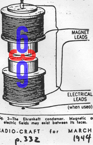
Felix Ehrenhaft: Magnetic Current --- 9 articles
it is the saturating part that caught my attention
 Last edited by MonsieurM; 09-29-2011, 09:25 PM.Signs and symbols -Confucius.
Comment
-
Folks,
I do not get it. Whenever you approach or attach a permanent magnet to a coil's ferromagnetic core, then the coil's inductance changes to a LOWER value, it does not increase. Core saturation means the original permeability reduces to a lower value (the operating point on the B/H curve is shifted towards the flattening sides where B cannot get higher any more howerer much amperturns you pump in. At over-excitation, a core can fully lose its permeability and the coil would behave as an air core coil.
So how is it meant?
Thanks, GyulaComment
-
this is just to have it as a reference:
from Felix Ehrenhaft: Magnetic Current --- 9 articles
found this while browsing Tesla's patentMagnetic Current ~
Ehrenhaft discovered that a magnetic current is surrounded by circular electric lines of force and that the magnetic charge of the magnet could be set free by making it release oxygen gas from acidulated water.
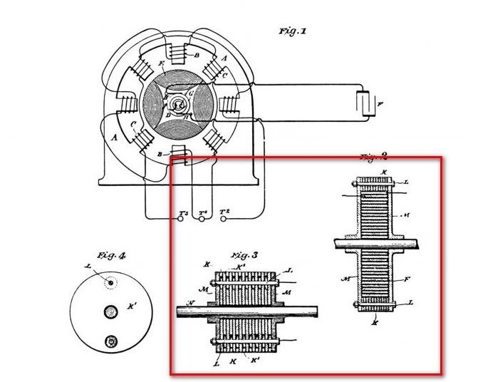
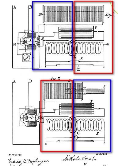
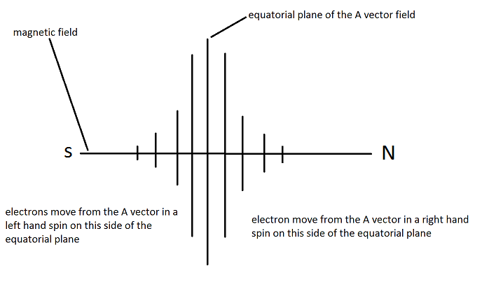
Signs and symbols -Confucius.Comment
-
Alright guys! I finally finished it! Well, there is a ton more I wanted to add, and it needs a lot of revision, but I am sick of it and wanted to get it posted. Feel free to read it and discuss what I present. Thanks in advance.

DavidComment
-
At over-excitation, a core can fully lose its permeability and the coil would behave as an air core coil.Originally posted by gyula View Post
GarryComment
-
Yes magnets reduce the inductance of a coil, in fact a generator coil does not have a constant L, and it is changing all the time.Originally posted by garrypm View PostComment
-
That is good David!Originally posted by Shadesz View Post
Phase shift of about 90 degree means completely no drag, but it seems that in the adams type rotor, Rod is getting acceleration, so the current is becoming assistive. If we utilize a system that makes use of the perpendicular force of the delayed current in the coil (eg a piston), then that current will work for us instead of against us or being neutral, that is what I think the Adams type rotor is all about. Think of mounting a magnet on a spring and making it oscillate really fast on top of a coil, don't you think that if the frequency of oscillation is enough it will become self running? I do think so.
BTW: if we take into consideration the phase lag caused by the core itself then we can go beyond 90 degrees of phase shift, although I think that 90 degrees of phase shift more than enough to lead to COP>1.Last edited by elias; 09-29-2011, 11:24 PM.Comment
-
@all , it would be nice if you could watch the following vid
particularly @ 1 min 40 s, keep in mind Muller set up..that angle is crucial
Nature by Numbers - YouTube
besides you'll learn in 4 min the golden mean and what it means in Nature
Signs and symbols -Confucius.Comment
-
Thanks.Originally posted by elias View Post
The kicker is, rod is seeing that acceleration without an inductor phase shift. Inductor phase shifts only happen in coils powered by electricity. Coils that pickup a magnetic field, pickup voltage and current at the same rate/time. Hence no inductor phase shifting.
Last edited by Shadesz; 09-30-2011, 03:06 AM.Comment
-
-
Nice! now we just need to figure out how to get it to use less power than no coil.Originally posted by qvision View Post
Comment

Comment