This forum is preserved as a permanent archive. The community continues at eMedia Press.

Announcement

Collapse
No announcement yet.

Joule Ringer!

Collapse
X
 
  • Filter
  • Time
  • Show
Clear All
new posts

  • ehsanco1062
    replied
    Originally posted by SkyWatcher View Post
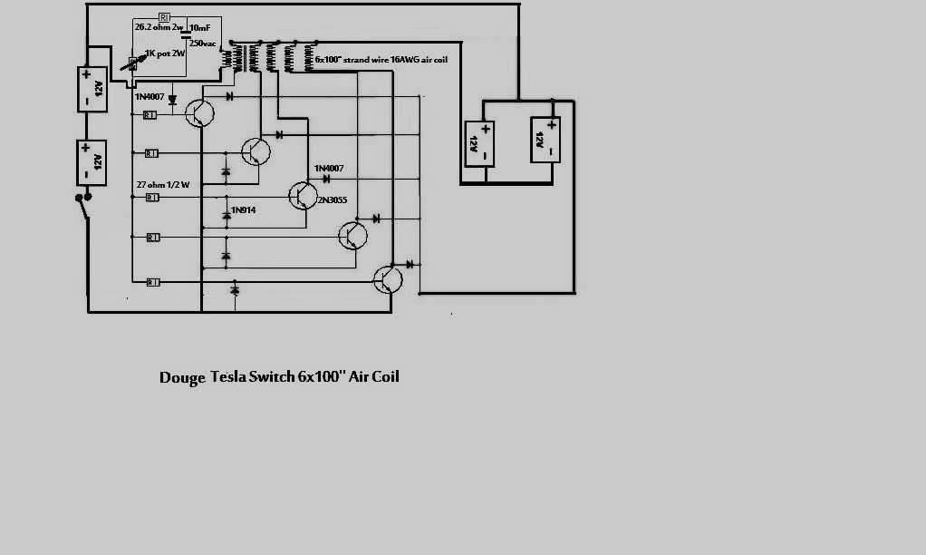
    Hi folks, Hi ehsan, I'm using the st13007 npn salvaged from something, can't remember, hehe.
    TRANSISTOR PWR NPN FAST HV TO220 - ST13007

    Something besides the wire length typo doesn't look right with that circuit diagram you posted ehsan, though i get the idea and have tried a version of that, though not with the cap diode addition.
    The negative going to transistor bases might be a problem with that circuit, need to switch polarities around on input and charge batteries or just use the positive going to base instead of negative.


    Hi All
    Hi Tyson

    You mean like this


    Also, Having experimented with similar circuits, one should go by how long the batteries power a load, no matter how good it appears the batteries have charged.
    peace love light
    tyson

    you are absolutely wright about that but i think this man also working for so long on this circuit until he came out with the modification maybe he took it from Patrick or maybe they both think about that at the same time any way the best way is to replicate and get result and make comparing between the two experiments.

    By the way did you try the air core coil and also make the comparing with this circuit because i have noticed that the air core give a good result.
    Thank you
    Ehsan

    Leave a comment:


  • Allen Burgess
    replied
    Batteries.

    I just sent a used Interstate lead acid battery to the junk yard that read 12.45 volts, but would'nt supply enough power to honk the horn.

    Leave a comment:


  • kcarring
    replied
    Originally posted by SkyWatcher View Post
    one should go by how long the batteries power a load, no matter how good it appears the batteries have charged.
    Amen to that statement. The Bedini circuit has frustrated me to almost quitting, given my "fluffy charge" results. I haven't given up yet though. I can't count the number of times I thought I had the right configuration, thought I was in the high 80's or even 90's for efficiency, only to see that despite a battery "holding" it's status (overnight for example) of 12.6-12.8 volts > the "power" wasn't there. Upon loading with a 10 watt or 20 watt Halogen Lamp, the cycle wasn't there; not like it'd be there with conventional or a solar charge. But I'll keep trying, ready to give it another shot, dug it out of the corner so to speak!

    Leave a comment:


  • SkyWatcher
    replied
    Hi folks, Hi ehsan, I'm using the st13007 npn salvaged from something, can't remember, hehe.
    TRANSISTOR PWR NPN FAST HV TO220 - ST13007

    Something besides the wire length typo doesn't look right with that circuit diagram you posted ehsan, though i get the idea and have tried a version of that, though not with the cap diode addition.
    The negative going to transistor bases might be a problem with that circuit, need to switch polarities around on input and charge batteries or just use the positive going to base instead of negative.
    Also, Having experimented with similar circuits, one should go by how long the batteries power a load, no matter how good it appears the batteries have charged.
    peace love light
    tyson
    Last edited by SkyWatcher; 12-22-2011, 11:11 PM.

    Leave a comment:


  • kcarring
    replied
    @Ehsan

    Is that really 100" or was that a typo and should read 100'. For strand length.

    Thanks.
    Kyle

    Leave a comment:


  • ehsanco1062
    replied
    Originally posted by SkyWatcher View Post
    Hi folks,
    @totoalas, I'm using power supply because I am needing to rejuvenate my batteries a bit, it seems my older radiant charger was not outputting enough voltage and so was not desulphating the batteries as well as it should have over time. One 7AH battery has already gained 6 watt hours capacity with only a couple cycles.
    Though the one I'm using now, does that very well. Also, I'm using a 100uf-100volt ac capacitor on base trigger.
    I also tried 2-5.6uf 160vac in parallel and that worked well also, though the 100 uf gives a little more kick.
    I use image shack and there is an embed in forum code line and that is copy and pasted into message to get pic to show up.
    @kcarring, my coil is 7 strands, 23awg, 4.6 ohms per strand, 1 trigger strand, 3 strands per transistor, only using two transistors at the moment.
    They are 400 volt-80watt transistors. My coil dimensions are 2" wide X 3" tall with 5/8" diameter ferrite core from audio crossovers.

    totoalas, that setup looks good.
    peace love light
    tyson
    tesla switch oscillation charger_0001.wmv - YouTube
    tesla switch oscillation charger_0001.wmv - YouTube

    I think you should see these videos
    He is also using the diode and cap modification

    Thank for your help with uploading pictures

    Good luck
    Ehsan

    Leave a comment:


  • totoalas
    replied
    Originally posted by SkyWatcher View Post
    Hi folks, oops my last post, first comments were meant for @ehsan, i was getting tired last night, hehe.
    Hi totoalas, as long as the solar panel can maintain its voltage and not sag below whatever voltage your radiant charger requires.
    So 4 watts sounds right for 267 milliamps draw.
    peace love light
    tyson
    thanks tyson
    One solar panel 10 by 20 cm 5 watts from China surely fits your recommendation

    Happy holidays
    totoalas

    Leave a comment:


  • SkyWatcher
    replied
    Hi folks, oops my last post, first comments were meant for @ehsan, i was getting tired last night, hehe.
    Hi totoalas, as long as the solar panel can maintain its voltage and not sag below whatever voltage your radiant charger requires.
    So 4 watts sounds right for 267 milliamps draw.
    peace love light
    tyson

    Leave a comment:


  • totoalas
    replied
    Homemade magnetic Amplifier by Minoly

    Homemade Magnetic Amplifiers.

    Leave a comment:


  • totoalas
    replied
    Originally posted by kcarring View Post
    Thankyou Sir
    Hi Kyle
    If am to top off the primary batt 12 v 7AH consuming 267 mA for charging for example 500 Ah batteries what size/ watts of solar panel can I use for Mobile charger like in a Car or a bus ??????
    thanks,

    totoalas

    Leave a comment:


  • kcarring
    replied
    Originally posted by SkyWatcher View Post
    @kcarring, my coil is 7 strands, 23awg, 4.6 ohms per strand, 1 trigger strand, 3 strands per transistor, only using two transistors at the moment.
    They are 400 volt-80watt transistors. My coil dimensions are 2" wide X 3" tall with 5/8" diameter ferrite core from audio crossovers.

    tyson
    Thankyou Sir

    Leave a comment:


  • SkyWatcher
    replied
    Hi folks,
    @totoalas, I'm using power supply because I am needing to rejuvenate my batteries a bit, it seems my older radiant charger was not outputting enough voltage and so was not desulphating the batteries as well as it should have over time. One 7AH battery has already gained 6 watt hours capacity with only a couple cycles.
    Though the one I'm using now, does that very well. Also, I'm using a 100uf-100volt ac capacitor on base trigger.
    I also tried 2-5.6uf 160vac in parallel and that worked well also, though the 100 uf gives a little more kick.
    I use image shack and there is an embed in forum code line and that is copy and pasted into message to get pic to show up.
    @kcarring, my coil is 7 strands, 23awg, 4.6 ohms per strand, 1 trigger strand, 3 strands per transistor, only using two transistors at the moment.
    They are 400 volt-80watt transistors. My coil dimensions are 2" wide X 3" tall with 5/8" diameter ferrite core from audio crossovers.

    totoalas, that setup looks good.
    peace love light
    tyson

    Leave a comment:


  • totoalas
    replied
    Originally posted by kcarring View Post
    @skywatcher totalas et all

    What sort of figures do you folks have on your coils... i see you are using 23 awg, what is the reading for ohm? Henries? number of turns / dimensions?

    Thanks!


    Uploaded with ImageShack.us

    Patrick set up 6 x 3.3 uf cap 6 coiler #23 50 m MJL21194
    wound in an old crt ferrite cone 8 and 4 cm dia
    will do the setup test w/ 12v 7ah batt on sat
    JB CHARGER INITIAL RUN W/O CAPS 221211 - YouTube
    totoalas
    Last edited by totoalas; 12-22-2011, 12:18 AM.

    Leave a comment:


  • kcarring
    replied
    @skywatcher totalas et all

    What sort of figures do you folks have on your coils... i see you are using 23 awg, what is the reading for ohm? Henries? number of turns / dimensions?

    Thanks!

    Leave a comment:


  • ehsanco1062
    replied
    Originally posted by SkyWatcher View Post
    Hi folks, Hi totoalas, thanks for the information and I hope you get good results.
    I am running some tests on mine, though as said, I'm only using two transistors, 3 strands per transistor.
    Right now, I'm using the main diode going to all bases, then 4-1kom 1 watt resistors in series/parallel for 1kohm total, then these resistors are in parallel with two 5.6uf ac capacitors in parallel for 11.2uf total.
    And I am using 300 ohm base resistors.
    I am not using any diodes from base to collector yet, or from emitter to collector, just the neons.
    Also I am not using the 10kohm and 20kohm resistors on first transistor stage.
    Though I may implement these other components to see if they benefit the charging or not.
    Though so far, the charging is very impressive and it is only using 280 milliamps input with the 13.8 volt power supply.
    When I switch on the power, the coil makes a kick or thumping sound as if it's really getting a nice trigger pulse from the capacitors and such and transistors are cool to the touch.
    peace love light
    tyson

    Leave a comment:

Working...
X
