Announcement

Collapse
No announcement yet.

Donald Smith Devices too good to be true

Collapse
X
 
  • Filter
  • Time
  • Show
Clear All
new posts

  • med.3012
    replied
    Originally posted by bugaian View Post
    Hello,

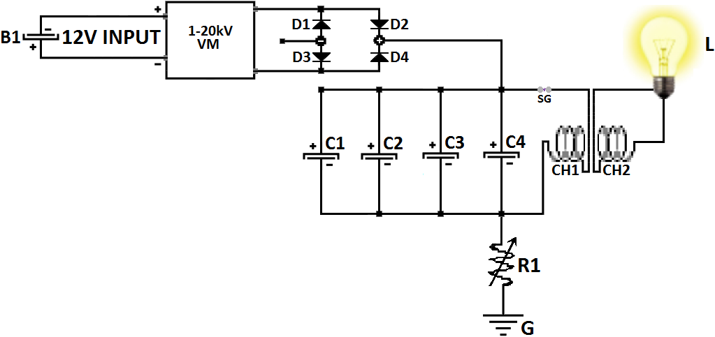
    schematics attached. On output I use 2 toroids for now.

    Before NST I have a variac(missing in schematics) and I can adjust voltage, spark gap will work OK at about 60-80V to NST. If I push it move voltage it just stops.

    I want to try your ETBC setup, need some more time to make one, also have seen etcb series on toroid video, may be thats the way to go to get better output.

    Thanks.


    welcome bugaian ,


    according the schematic you are loading the NST directly without using a capacitor , in this case you need a large spark for large output and this load the secondary of NST to high level and make the winding warm so if there's a kind of electronic control it will see transformer overloading, so i propose to use a capacitor to bypass this problem , about serial ETBC we need a large core to work with, ferrite or Metglas are the two good option.

    Leave a comment:


  • bugaian
    replied
    Originally posted by med.3012 View Post
    please if you can post a basic schematic for connection to see what's going on ?
    Hello,

    schematics attached. On output I use 2 toroids for now.

    Before NST I have a variac(missing in schematics) and I can adjust voltage, spark gap will work OK at about 60-80V to NST. If I push it move voltage it just stops.

    I want to try your ETBC setup, need some more time to make one, also have seen etcb series on toroid video, may be thats the way to go to get better output.

    Thanks.
    Attached Files

    Leave a comment:


  • med.3012
    replied
    Originally posted by bugaian View Post
    Hello to all,

    thanks for hard work and good information posted in this thread.

    I was able to replicate Don's basic design using NST( 37Khz at 6kV) the only problem I have is that I am at a limit with spark gap. If gap is bigger a bit I get very useful output, but the problem is after a 15-30 minutes run the NST would shut down.

    Now running it at a limited spark gap power and getting about 200W, if I try to get more adjusting spark gap distance it just shuts down.

    Any ideas of how to fool the NST? I tried wih grounding and without grounding it my result are same.

    Anybody having same experiences?

    Thanks for sharing.


    please if you can post a basic schematic for connection to see what's going on ?

    Leave a comment:


  • bugaian
    replied
    Any method to avoid NST shut down?

    Hello to all,

    thanks for hard work and good information posted in this thread.

    I was able to replicate Don's basic design using NST( 37Khz at 6kV) the only problem I have is that I am at a limit with spark gap. If gap is bigger a bit I get very useful output, but the problem is after a 15-30 minutes run the NST would shut down.

    Now running it at a limited spark gap power and getting about 200W, if I try to get more adjusting spark gap distance it just shuts down.

    Any ideas of how to fool the NST? I tried wih grounding and without grounding it my result are same.

    Anybody having same experiences?

    Thanks for sharing.
    Last edited by bugaian; 06-21-2016, 05:25 PM.

    Leave a comment:


  • med.3012
    replied
    Originally posted by Gedfire View Post
    Well Sir,

    It appears that it was a conceptual model of the more advance devices Don said he cannot disclose due to contractual arrangements.


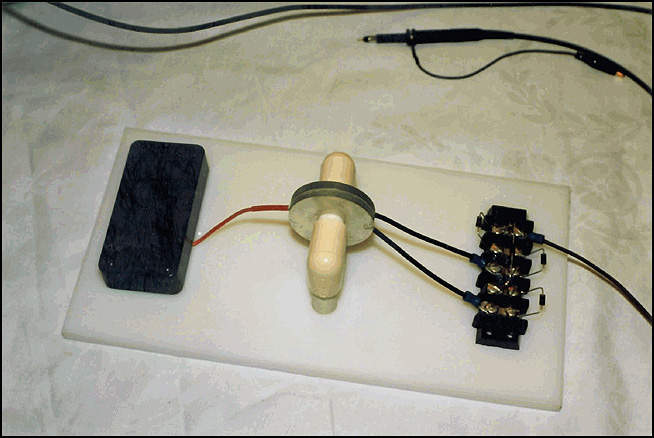
    The black box or cuboid on the left of the last pic may be a signal and or frequency generator.Like this one: Lab Brick FAQ | Vaunix LMS Programmable Signal Generators

    The middle piece is an ultrasonic device made from the Barium.He is using the possibly tuned device to pulse the two outer pieces.The ultrasonic frequencies will induce mechanic stress on the inner piezoelectric material which will vibrate to the frequency of the signal generator.The two outer pieces of piezo discs will be impacted by the vibrating of contracting and relaxing inner disc and a voltage will be generated .This is taken to a bridge rectifier with a capacitor for DC.Here is a book:https://books.google.com.jm/books?id...ectret&f=false

    AWESOME stuff.I know Patrick Kelly will look this up and publish it.

    I think this is what this Japanese inventor the eccentric Yoshiro Nakamatsu uses to power his house.Just much larger.


    Thanks for this info.

    Leave a comment:


  • Gedfire
    replied
    Originally posted by med.3012 View Post
    Hello Gedfire,

    i have no idea about this
    Well Sir,

    It appears that it was a conceptual model of the more advance devices Don said he cannot disclose due to contractual arrangements.


    The black box or cuboid on the left of the last pic may be a signal and or frequency generator.Like this one: Lab Brick FAQ | Vaunix LMS Programmable Signal Generators

    The middle piece is an ultrasonic device made from the Barium.He is using the possibly tuned device to pulse the two outer pieces.The ultrasonic frequencies will induce mechanic stress on the inner piezoelectric material which will vibrate to the frequency of the signal generator.The two outer pieces of piezo discs will be impacted by the vibrating of contracting and relaxing inner disc and a voltage will be generated .This is taken to a bridge rectifier with a capacitor for DC.Here is a book:https://books.google.com.jm/books?id...ectret&f=false

    AWESOME stuff.I know Patrick Kelly will look this up and publish it.

    I think this is what this Japanese inventor the eccentric Yoshiro Nakamatsu uses to power his house.Just much larger.
    Last edited by Gedfire; 06-12-2016, 12:41 AM.

    Leave a comment:


  • med.3012
    replied
    Hello Gedfire,

    i have no idea about this

    Leave a comment:


  • Gedfire
    replied
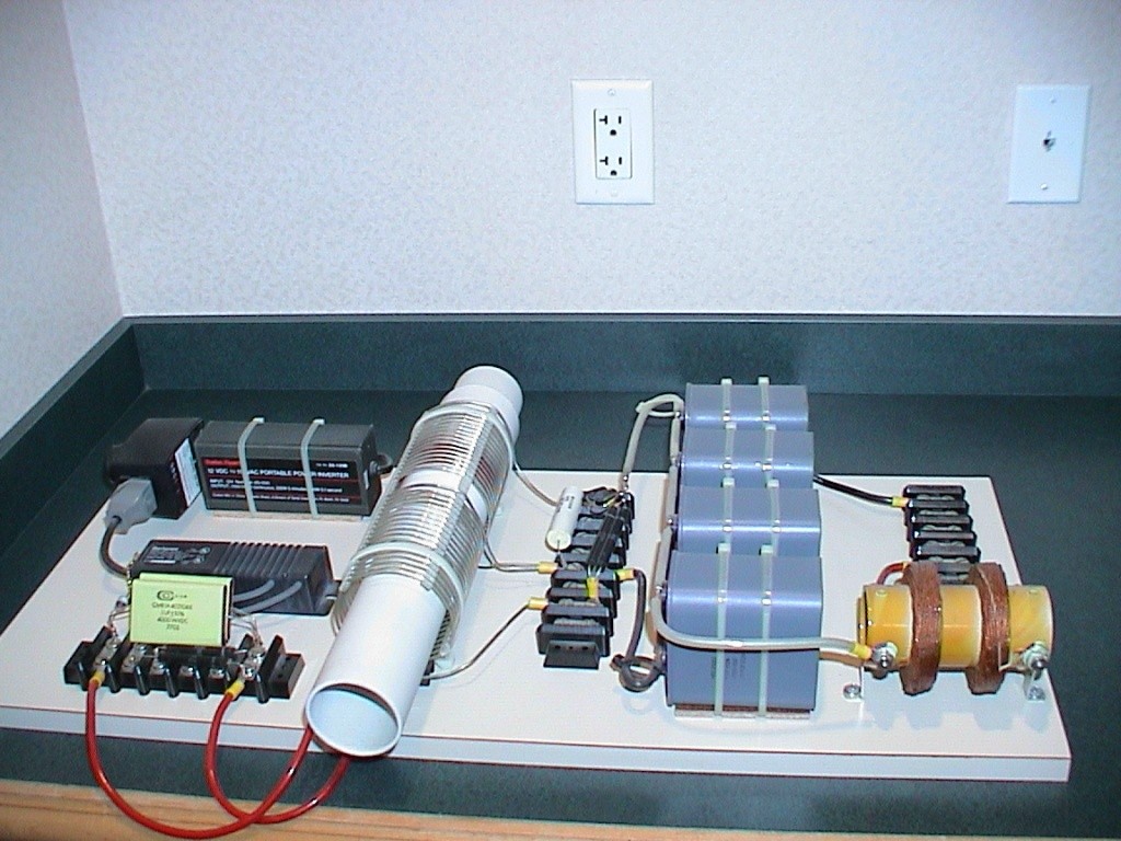
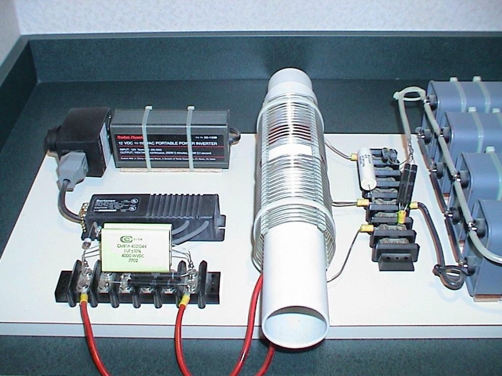
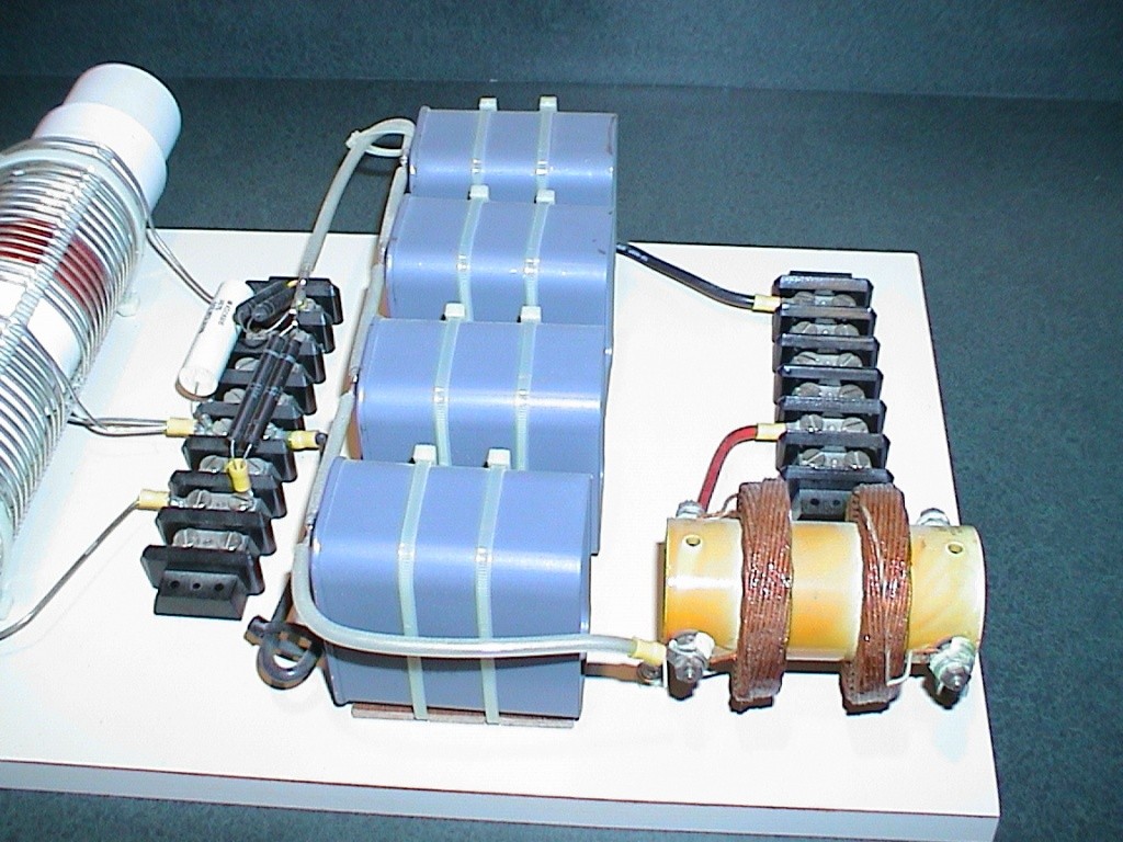
    Piezoelectric or an Electret Device?

    Originally posted by soundiceuk View Post


    Hey All,

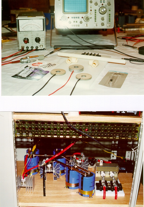
    Can anyone give a reasonable description of what this device is and how it works.This was posted by Soundiceuk many moons ago.That's device 2,4 and 5 in the picture.The one with the discs.Barium titanate piezoelectric ceramics,Barium titanate piezoelectric ceramics_Company News_UCE ultrasonic co.,Ltd

    I now have renewed interest in it.I have my own theories but other perspectives are important.

    Oh of course some of the parts are some sort of piezoelectric stuff.

    Thanks
    Last edited by Gedfire; 06-11-2016, 07:07 PM.

    Leave a comment:


  • Gedfire
    replied
    Lol

    Originally posted by soundiceuk View Post
    Hi folks, lets bring a close to this.

    Don's briefcase device was extremely efficient for lighting but was not self sustaining or even COP > 2.0


    Don Smith 2016:


    Video:


    Good to see you Soundiceuk! Nope,there will be other episodes!

    Leave a comment:


  • Dave45
    replied
    Originally posted by soundiceuk View Post
    Hi folks, lets bring a close to this.

    Don's briefcase device was extremely efficient for lighting but was not self sustaining or even COP > 2.0


    Don Smith 2016:


    Video:


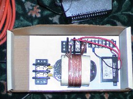
    The schematic does not match the hardware. The primary is inside the two secondaries.

    Leave a comment:


  • med.3012
    replied
    hello everyone


    just to post something interesting about the resonance energy device, a new video published show a very promising technology called serial ETBC, a technique that can square your output power ...

    good watching


    [VIDEO]https://www.youtube.com/watch?v=a0FNZZywgng&feature=youtu.be[/VIDEO]


    or click here https://www.youtube.com/watch?v=a0FN...ature=youtu.be

    Leave a comment:


  • soundiceuk
    replied
    Hi folks, lets bring a close to this.

    Don's briefcase device was extremely efficient for lighting but was not self sustaining or even COP > 2.0


    Don Smith 2016:


    Video:


    Leave a comment:


  • med.3012
    replied
    Originally posted by a.king21 View Post
    There was no input, except the one touch to charge the system. You are looking at output - no input. I do not claim ou is because the Tesla switch was driven separately. It was a proof of concept experiment. I even used dc caps, and it worked. Also the camera could not record the ne2 correctly. It was on continuously


    Ok thanks for the explanation.

    Leave a comment:


  • a.king21
    replied
    Originally posted by med.3012 View Post
    did you measured the INPUT versus the OUTPUT?
    There was no input, except the one touch to charge the system. You are looking at output - no input. I do not claim ou is because the Tesla switch was driven separately. It was a proof of concept experiment. I even used dc caps, and it worked. Also the camera could not record the ne2 correctly. It was on continuously
    Last edited by a.king21; 06-05-2016, 03:39 PM.

    Leave a comment:


  • tswift
    replied
    Yes, I got that when I tried the link too, it mistakenly had an extra "http://" in the URL. I edited the post and should it work now, or you can just copy and paste the text into a new tab to get it correctly.

    Leave a comment:

Working...
X