Announcement

Collapse
No announcement yet.

Gray Tube Replication

Collapse
X
 
  • Filter
  • Time
  • Show
Clear All
new posts

  • Spokane1
    replied
    E. V. Gray History Errata

    Originally posted by Aaron View Post


    Go here for the homepage: The Real History of the Ed Gray Motor

    Mark - if you have any concerns or corrections for the homepage, please email them to Peter or I and we'll get them changed ASAP!

    There you go everyone - Mark's presentation on The Real History of the Ed Gray Motor. It is not a "how to" on the technology itself, but a history investigative lecture on what Mark was able to learn about the path that Ed Gray took. It is highly informative and very entertaining as well!
    Aaron,

    The only correction is that the FCC confiscated the EMA6 in 1977 and not in 1979. Other than that all of the promotion material looks great. I have already sent Peter an email to this effect.

    Fellow E.V. Gray Reseachers who read this Blog,

    The DVD download that is being offered is the most accurate history available to date.

    If you are interested in my technical speculations on how this equipment actually worked then drop me an email at [email protected] and I shall send you a 25 page (or so) Word document that covers several major clues as I see them plus the theory as to where I might go from here. The paper follows the same information as discussed in the YouTube video mentioned above in a previous post.


    Mark McKay

    Leave a comment:


  • Aaron
    replied
    The Real History of the Ed Gray Motor by Mark McKay


    Go here for the homepage: The Real History of the Ed Gray Motor

    Mark - if you have any concerns or corrections for the homepage, please email them to Peter or I and we'll get them changed ASAP!

    There you go everyone - Mark's presentation on The Real History of the Ed Gray Motor. It is not a "how to" on the technology itself, but a history investigative lecture on what Mark was able to learn about the path that Ed Gray took. It is highly informative and very entertaining as well!

    Leave a comment:


  • Aaron
    replied
    Ed Gray's Motor presentation by Mark McKay

    Tomorrow, Mark McKay's presentation on the history of the Ed Gray motor will be available.

    Leave a comment:


  • tachyon
    replied
    You're giving me a headache and I've just woken up lamare.. there are simpler ways to explain all this with fluid dynamics.. I guess you didn't read another thread.

    Leave a comment:


  • ekpod
    replied
    The motor here sends back each pulse to the capacitor.

    Last edited by ekpod; 09-29-2012, 01:44 PM.

    Leave a comment:


  • giqift
    replied

    Leave a comment:


  • giqift
    replied
    Great tube project Aaron... when the coil emits high voltage plasma and the 25KV blocking rectifier on the LV side
    says NO WAY and gets the capacitor to froth over the gap in its midst. Hey and the gap on the other side of the coil
    to (-)LV and Ground is then where the bulb is right?

    Leave a comment:


  • Etherichead
    replied
    Great video and insight, your R&D is greatly appreciated, as this energy concept is in my opinion the greatest discovery of all time. I just want to give credit where credit is due, E.V. Gray is not the inventor, Marvin Cole is, as he was the chief engineer and developer of the system, after he stepped out, Gray was never able to produce the results on his own. It should be called "Cole's Tube", this and more is in Lindemann's new book "The Real History of the E.V. Gray Motor" I eagerly await to read it. Thank you for your post's, keep up the great work!

    Leave a comment:


  • Spokane1
    replied
    Impromptu Gray Theory Lecture

    Dear Folks,

    Here is a YouTube link to a 37 minute video recording of me sharing my ideas about the nature of the E.V. Gray converter technology as best determined so far from the avaliable history. This took place after my E.V. Gray historical presentation at the the July Bedini-Lindemann conference.

    Thanks to whoever provided this recording.

    Again this is mostly speculation on my part and is the best I can come up with so far.


    I hope the link works and that you might get some usable ideas from this discussion.

    Mark McKay

    Leave a comment:


  • Spokane1
    replied
    Stored Magnetic Fields - Short or Long Time Frames

    Dear lamare,

    The concept of stored magnetic fields is used extensively in MRI machines. Here a large coil made of super conducting Nirobium is charged with DC current over a period of time. Once the maximum current level is reached the coil is shorted out and the trapped current continues to flow. No more energy is needed to matain a 2-5 Tesla field for that bias axis condition. However, this is done at liquid Helium temperatures.

    The magnetic field will maintain itself for years until the coil is taken out of service. The procedure for discharging this stored eneregy is done slowly with many safety precatuions. I'm sure that a detailed analysis of the magnitude of the stored energy has never been done.

    With this concept in mind and the idea that a closed magnetic field might be able to couple with the zero-point (or what every one calls it) then does an apparatus like the one described above absorb more OU in years of opperation as compared to the various demonstration motors that only maintain a closed field for a few milliseconds?

    Spokane1

    Leave a comment:


  • lamare
    replied
    Leedskalnin principle

    The big question is whether or not it is possible to gain energy trough a closed magnetic loop according to the principle that a magnetic field can be locked inside an iron core.

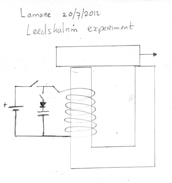
    This could be investigated with an iron core coil with a U shaped core and a top bar as Leedskalnin used:


    The idea is that if you energize the coil with the bar in the position shown in the image and then disconnect the battery, that a magnetic field will be present within the looped core.

    So, when you then connect a capacitor trough a diode and rip the bar off, this energy is discharged into the capacitor and you can measure a voltage. (Oops, I have drawn the diode in the wrong direction).

    You can repeat the same experiment with the bar in the position whereby it is completely aligned with the U. In both cases one expects to see the same voltage on the capacitor.

    However, there might be a significant difference if one energizes the coil with the bar in the shown position, then disconnect the battery and then gently move the bar to the right, until it is completely aligned with the U.

    At that point, one connects the capacitor and rips the bar off the U, so you get a discharge. If my theory is correct, you should now see a significantly higher voltage.

    The idea is that a closed loop iron core is able to pick up energy from the aether and that the magnetic field locked inside will be constant in magnitude along the closed loop. With the bar in the drawn position, there all the fluxlines are forced trough the small connection area between the bar and the U core, and will thus result in a stronger magnetic field than in the situation whereby the core is energized with the bar completely covering the U core.

    Now if the core is able to pick up energy from the aether and it tends to maintain an already established magnetic field strength, then moving the bar over the U core should result in this stronger magnetic field being extended all trough the core, hence containing more energy.

    So, if you would then rip the bar of and discharge the energy, you should see a bigger voltage on the cap if this theory is correct.

    And if it is, we now have a principle which we can use to build COP>1 motors....

    Update:

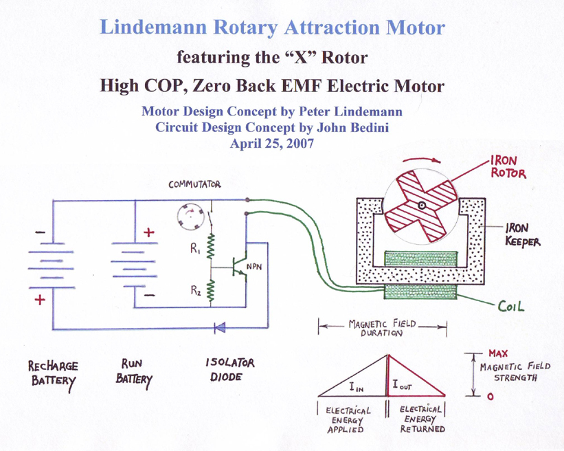
    Peter Lindemann published a Rotary Attraction Motor that may be operated along this principle:
    Energetic Science Ministries | Bob Teal | Magnipulsion


    Rotary Attraction Motor Update


    The idea would then be to (strongly pulse) magnetize the coil at the moment the rotor enters contact with the stator and de-magnetize at the moment rotor and stator face one another, returning both additional energy AND preventing further attraction from slowing your motor down.
    Last edited by lamare; 07-20-2012, 08:38 AM.

    Leave a comment:


  • lamare
    replied
    Been thinking about Leedskalnin perpetual motion holder:

    Edward Leedskalnin's Perpetual Motion Holder

    This is very interesting. What this shows is that you can magnetize a closed loop magnetic core such that it remains magnetized even though you don't have to feed any current trough the coil anymore. Now if there is a sufficiently small gap in between rotor and stator, we should be able to create the same effect, albeit for a limited time. Say in the order of milli-seconds or seconds instead of hours or days - which is also limited of course, but you get the point.

    If this is the principle, then you first of all want to establish as strong a magnetic field as possible, hence the pulsed high voltage and thus (short) high current discharge, and you want the core to maintain the field, which means you have to prevent the coil from sparking because of the BEMF.

    Now if my suspicion is right in that a coil can only interact with a contracting or expanding magnetic field and a magnetic field can apparently be contained in a closed loop core, then there likely is a considerable difference in terms of BEMF reaction between a coil around a closed loop core and a coil around an open core.

    An open core cannot contain a magnetic field and that means that when you shut of the current trough your coil, it MUST discharge it's magnetic energy and you get a spike.

    A closed core can contain a (D.C.) magnetic field and thus it does NOT have to discharge it's energy. Hence when you shut of the current trough such a coil, you would expect the BEMF to be sufficiently weaker in magnitude, while it likely shows a damped oscillation meanwhile stabilizing the field inside the core, whereby the energy is contracted into the core.

    Hence it is possible to magnetize a closed loop core, as long as you make sure the BEMF, which would show a damping oscillation, can not discharge electrically.

    A sudden discharge of a cap into a coil trough a diode or transistor that is able to withstand the BEMF voltage would be all that is needed in order to create a semi-permanent magnetic field inside a closed loop core. Only once you rip the loop apart, you get a strong BEMF which MUST discharge and thus can create high voltages.

    So, you would get a system that is Bedini-like but with a(n almost) closed core, only you can probably not use a diode to capture the BEMF, because during the build-up of the magnetic field the BEMF should not be allowed to discharge. It should only be allowed to discharge once ripping the loop open, which means you would probably need a transistor for that. One tends to think in the direction of a opto-coupler steered (relatively) heavy duty transistor instead of a diode.

    Now the interesting thing is that such a semi-permanent magnetic field creates an attracting force across a small gap in between the parts of the looped core. The smaller the gap, the bigger the force and the less leakage. In other words: this principle allows you to create an attracting force, for which you don't have to pay in terms of energy, because once the loop is opened, you can retrieve most of the energy by capturing the BEMF pulse. Now this HAS to be an attracting force, because that is the only way by which you can contract a magnetic field into a closed loop core. So, it this is the principle indeed, there HAS to be a closed magnetic loop in the motor somewhere, which delivers the actual power, which is converted by the atoms that sustain the magnetic field in the core from energy that is already present in the aether a.k.a. the zero-point field, along the lines of Prof. Turtur's theory.

    In order to investigate this phenomenon, one would take such a Leedskalnin core and investigate the difference between a closed core and a core with a small gap, like with a sheet of paper in between. One could also measure the attracting force using a piezo electric sensor:
    Piezoelectric sensor - Wikipedia, the free encyclopedia


    Update:

    I also posted some on Ufo's thread on the connection of his stuff to Gray's stuff:


    Last edited by lamare; 07-17-2012, 08:04 AM.

    Leave a comment:


  • lamare
    replied
    Originally posted by lamare View Post
    The most fundamental issue regarding all seemingly OU systems is that there MUST be at least TWO separate energy flows, whereby one flow comes for free and the other one is used to influence the energy flow that comes for free. The law of conservation of energy is a fundamental one and it does hold.

    So, in whatever machine is created that appears to generate energy out of nothing, there is an energy source that is being tapped.

    One of the most simple free energy system are the commercially available heat pumps, which are used to extract heat out of the earth. The trick is that it takes less energy to operate the energy pump than the amount of energy which is extracted in the form of heat out of the earth.

    For electro-magnetic systems, the interesting fact described by Prof. Turtur ( http://www.gsjournal.net/old/physics/turtur1e.pdf ) is that both the electrostatic and magnetic fields are powered by charge carriers, electrons in practice, which convert energy out of the medium into these fields. So, there you have your energy source. Both the magnetic and electric fields can be considered to be energy sources, because they are powered by the medium or the vacuum in Bearden's terms.

    Now in a closed electric system, there is a fixed amount of electrons (even though these can probably be created at will, which appears to actually happen in the heated element of a radio tube, but that's another story), which means that however you let these electrons flow in/out your battery, you can never gain energy, unless you manage to tap it from some other energy source.

    So, as long as you keep thinking in terms of charging/discharging coil (windings) as isolated systems, there ain't no way you can account for any surplus energy. And that is the reason I said your witch sucked.

    However, when you have two separate energy flows, you can use one energy flow to influence the other, without paying for that in terms of energy, except for some losses. And since mother nature always strives to return balance, all you need to do is bring a dynamic balanced system out of balance in order for some energy flow to do useful work.

    The bad news is that this will always cost you some energy, but as long as at the end of the line you manage to get more energy back from mother nature as the energy you have to spend in order to get it, all is nice and well.


    I still see that You are looking at my System as a "Handicap" by Permanent Magnet Stators "Limited" use, as the "Only Way Out" / Not Scalable"...System...
    It definitely helps a lot to start studying a system with a PM stator, because then you know that the PM field does not vary (much) in strength, which makes it possible to recognize that there are two interacting magnetic fields. One created by your stator and one by your rotor coils.

    However, the principle that a magnetic field can be amplified and guided by an iron core also applies to electro-magnetic stators. If they are D.C., then the same line of reasoning still applies. If they are A.C., things get more complicated, but if a large part of the magnetic field trough the rotor originates from the stator magnets and it is to a large degree only re-directed from one pole to the next by your rotor coil, then the energy flows can probably still be considered to be separate to a large degree.

    However, there are still a lot of questions about how magnetic fields behave in an iron core. Leedskalnin's perpetual motion holder demonstrates that even when the coil around a closed-loop iron core is being disconnected from a battery, the magnetism can remain inside the core.

    Edward Leedskalnin's Perpetual Motion Holder
    Researchers have continued to be interested in this device because it defies natural laws of physics and is unexplainable by conventionally excepted electromagnetic theory.
    And in one of his lectures (iirc together with Carlson), Eric Dollard shows that we still do not really understand how a transformer actually works. If the magnetic field stays within the core, how can it influence a coil wrapped around it?

    It appears to me that the answer is to be found once again in balance v.s. disbalance. I suspect that the magnetic field inside an iron core only interacts with it's environment (like a coil) when there is some disbalance being introduced, either by a coil or by ripping the iron core apart, such as in the Leedskalnin experiment.
    What is very interesting in relation to Ufo's work is that there is also asymmetry in Gray's motor design:

    US Patent 3,890,548 Edwin Gray "Pulsed Capacitor Discharge Electric Engine"


    At first glance, it looks like the asymmetry is in the 3 pole rotor, but here you do not have a more or less continuous path for the magnetic field to follow trough the rotor.

    However, the magnetic field must go somewhere and tends to establish a closed loop. It appears that mother nature does us a favor under certain conditions, which is that a magnetic field is amplified by an iron core, because charge carriers do extract energy from the aether and emit that in the shape of a magnetic field. So, it appears that we have a principle by which to extract energy from the aether by means of the establishment of a closed magnetic loop.

    On the rotor there are two sets of magnets in line, which both consist of a major and a minor magnet.

    One could guess that these sets are fired in the opposite polarity and thus a magnetic field can establish itself inside the rotor, along the length of the rotor.

    The question is: how are the major and minor magnets fired with respect to one another and at what moment in the cycle are they fired?

    Another question is: could it be that we are looking at the superposition of a D.C., quasi permanent, attracting magnetic field, which is disturbed at the moment the coils fire?

    Update: According to the patent description, the major and minor coils are fired independently, and always either the major or the minor coils, at the moments they face one another. So there goes my theory of major/minor coils having something to do with Wheatstone's delay of a high-speed pulse....

    Update 2: It appears that if the minor coils fire at 13 1/3 degrees from the top position in the figure, that it may possibly induce an attracting force between the major cores 120a and 121. Have to think about this further, because you also have the pairs along the length section. One would expect mother nature to find the shortest closed loops that it can find, so it can create attracting forces....

    Update 3: The degrees at which the coils fire are visible in the figure. It appears as though the minor coils are producing distracting "pushing" forces because they are fired while the cores face one another directly, while the major coils produce an attracting force, because these are not directly over one another at 26 2/3 degrees.

    If that is correct, the power is developed by the major attracting coils, while the minor coils are meant to push the rotor over the dead points, whereby the energy spend in the minor coils is mostly losses (except if they indeed already pre-magnetize the major coils), while the major coils can show a gain along the principle extrapolated from Leedskalnin's experiment (see below). If that is correct, one would expect the major coils to be somehow discharged/demagnetized at around 40 degrees in the cycle.

    The latter is possible, because if the major coil fires at the point the major coils enter contact, you get a build up of magnetic force in some closed loop, until the major coils face one another completely. From that moment, the field starts collapsing, producing a BEMF, which may generate a high voltage, which can be discharged trough a spark gap, so the attracting force is neutralized an cannot hinder the further rotation of the rotor. IIRC, there is an "overshoot" spark gap somewhere in the design...

    From the figure, it appears as though the major an minor coils fire almost at the same time after all...

    And if there is to be a closed magnetic loop trough the rotor, one would expect two of the major coils to have the same polarity, while one has an opposing polarity and/or the two sets of coils along the length direction having an opposite polarity. I would guess the latter to be the case....
    Last edited by lamare; 07-17-2012, 09:37 AM.

    Leave a comment:


  • lamare
    replied
    Originally posted by Spokane1 View Post
    Dear lamare,

    That certainly is a nice write up on Gary's past work. I suppose it took you several hours to compose all that technical writing.

    I was wondering if your commentary included Gary's most recent work? Just before the conference Gary sent me a large envelope and some large 8"x10" color photos of his latest exploration. Did you happen to get a copy of that report?

    Mark McKay
    Nope, don't have that. Would be nice if it could be published, but even if it cannot be published I would love to have it.

    However, we may find some more clues in the system currently being disclosed by UfoPolitics on his thread. I commented some over there, and the idea of creating a disbalance in an asymmetric system is intriguing:

    Originally posted by lamare View Post
    Originally posted by Ufopolitics View Post
    Oh!, I have a great present here for you all to have lots of fun with...Well "presents for some...and kind of "Head Aches" for some Classic Symmetrical Physics "Experts"...


    <snip>

    So... it should not turn Right Lamar?...However, it DOES!...and AWESOME!!

    Now, why do you think that Happens Lamar?...If "supposedly" this Coils-Inductors "never" change their polarity??!!...
    <snip>

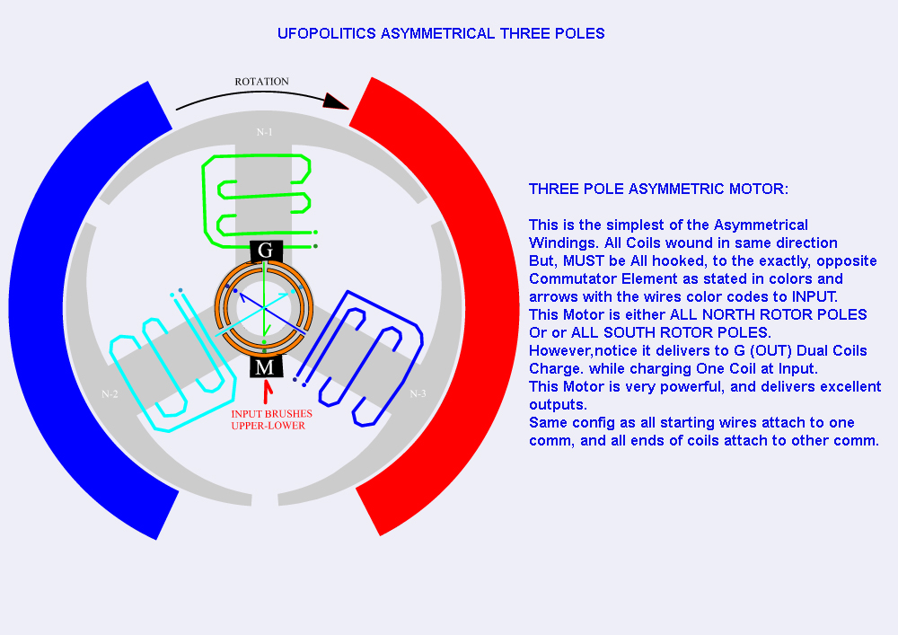
    All right. What you are looking at in this picture is that N2 and N3 are not activated from the battery. Therefore, their polarity is being determined by the permanent magnet. In other words: N2 is S (induced by the N of the PM) and N3 is N (induced by the S of the PM).

    In the current position of the rotor, in the case there would be no current flowing trough the N1 coil, N1 would be neutral in the centre, while you would have an S at the left (induced by the N of the PM at the left) and a N at the right (induced by the S of the PM at the right). In that case, most of the magnetic fieldlines would go trough N2 and N3, and some trough the top of N1.

    The firing of N1 makes it a N, which is attracked by the S of the PM, and the closer it gets to the magnet, the stronger the N becomes, because the PM amplifies the pole already induced by the coil, because iron is being attracted by a magnet, by which process the iron gets magnetized by the PM by magnetic induction.

    That is all the pretty much like with a normal motor.

    Now I realize that the big difference is that N2 and N3 are also connected to a brush on the commutator, most notably during that part of the cycle where the pole moves in/out of the PM, causing a collapsing or building of a magnetic field in the core within the coil, which normally induces a high voltage in the coil, which gives a spark in normal motors.

    And THAT is the problem with a normal motor, a problem that has been overlooked by everyone.

    You see, the problem with a sparking coil is that you get very powerful phenomena taking place, which Steinmetz called "transients" about which he wrote a whole book:
    Theory and calculation of transient electric phenomena and oscillations : Steinmetz, Charles Proteus, 1865-1923 : Free Download & Streaming : Internet Archive

    And you only need to look at Edwin Gray's motor, which somehow harnassed these powerful transients by discharging a HV cap trough a spark gap into his coils, to realize that unwanted/uncontrolled sparks are a big headache in motors with coils. They generate much more powerfull (negative) effects than is being realized.

    Now because your coils are connected to your generator brushes during that part of the cycle where the pole moves out of reach of the PM, you don't get these sparks and thus do not get these very powerfull transients that ruin the party in normally wired motors.

    If this is correct, then I would say that you will not be able to have the motor power itself just by using the generator windings to re-charge your batteries. BUT you have all the torque on the shaft which you can use almost for free, so if you connect a separate generator to the shaft, you may very well be able to create a self-runner.

    Originally posted by lamare View Post
    Yes, that is about the idea. It is very hard to connect al the dots theoretically, but I see a certain analogy with Milkovic' pendulum:

    Veljko Milkovic - Home Page - Official presentation of the researcher and inventor Veljko Milkovic

    I appears to me that the way UFO is working, is indeed much more like working with the already present field of the permanent magnet, instead of fighting it frontally.

    Just like with Milkovic' pendulum, you are fiddling with the balance of the system, which enables you to extract energy out of a "DC" field, either a permanent magnetic field or the gravity field in Milkovic' case.

    I suspect that when you analyze this completely trough, it can somehow be seen as "parameter variation", whereby you vary some aspect of a system by which you introduce asymmetry. This means that you have an oscillating system (rotation is one form of oscillation) whereby you change a parameter, like for example the inductance or capacitance of the oscillator or in the case of Milovic the length of the long arm.

    The idea is then that the changing of that parameter takes you very little energy, while it introduces a disbalance in the oscillator which enables the oscillator to pick up energy from the aether. That is what Bearden refers to as "regauging".

    This has been theoretically described in Russian by Mandelstam and Papalexi in the 1930s, a/o referred to by Dollard, which has been recently translated:

    Directory contents of /pdf/Reference_Material/Mandelstam_Papalexi/

    In the case of these motors, you have a rotor which is asymmetric. Since the field of the PM is DC, but it is a dynamic force, it looks like you influence the path the field of the PM takes by means of firing a coil on the rotor.

    As far as I can tell, there is one pole that is (almost) completely within the PM, while there are two that are in a process of magnetizing/demagnetizing because of leaving/entering the PM. Since the PM is DC and there is one pole (almost) completely within the PM's influence, the magnetizing/demagnetizing of the other poles must be (largely) in balance.

    Now since you influence this balance by the firing of the coil and the PM is DC, it appears you can see that influencing as some parameter change indeed. You could perhaps see it as akin to lowering the "magnetic resistance" of the pole you want to be attacked by the PM.

    So, I do see some theoritical basis on why this system could be COP > 1, but I doubt if you will be able to make it self running just on the generator windings alone. Because if indeed the working principle is parameter change, then all the energy you can get back from the generator winding is the energy spent on changing the parameter, the "magnetic conductivity" of one of the poles.

    However, that pole is rotating within a magnetic field of the PM, which makes things very complicated. So, there are also arguments that the rotator coils could pick up some energy from that field. However, if the motor is properly constructed, the idea is that most of the magnetic force is turned into useable torque.

    To sum this up: I do see some very interesting possibilities that this design might cause a revolution, but practice will have to tell. Theory can only get you so far....
    Break - more to follow.
    Last edited by lamare; 07-18-2012, 07:08 PM. Reason: image recovered.

    Leave a comment:


  • Spokane1
    replied
    Gary Magratten's Work

    Dear lamare,

    That certainly is a nice write up on Gary's past work. I suppose it took you several hours to compose all that technical writing.

    I was wondering if your commentary included Gary's most recent work? Just before the conference Gary sent me a large envelope and some large 8"x10" color photos of his latest exploration. Did you happen to get a copy of that report?

    Mark McKay

    Leave a comment:

Working...
X