
Gary Magratten published a patent for a device which is derived from Gray technology:
Electron avalanche drive circuit - Magratten, Gary J.

This may give some further clues...
Edwin V. Gray employed a high voltage spark gap exposed to open air in his U.S. Pat. No. 3,890,548 entitled, Pulsed Capacitor Discharge Electric Engine issued Jun. 17, 1975. The purpose of the spark gap was to provide accurate timing for the discharge of capacitors. At the time, those skilled in the art were unaware that electron avalanche, as developed in a high voltage spark gap exposed to open air, could increase the current to the inductive load. Carefull examination of the placement of the spark gap in the patent drawings show the spark gap after the inductive load rather that before it. This prevented additional current from electron avalanche from being employed to the inductive load.
At present there is no known electric power drive circuit operated on the principle of electron avalanche as developed in a spark gap exposed to open air in order to increase the current delivered to the load. The employment of electron avalanche as developed in a high voltage spark gap exposed to open air for the delivery of additional current to an inductive load is unobvious to all skilled in the art. The result achieved by the employment of the invention for the delivery of increased current to the inductive load is new, unexpected and superior to all prior art.
The prior art referenced were inoperative in that they did not employ electron avalanche in a practical way for the delivery of increased current to the load. The prior art referenced were also inoperative in that they were impossible to succesfully be reconstructed. Another novel mechanism associated with the invention is the use of a high speed, unidirectional switching system to release the additional current developed by electron avalanche from the main circuit.
At present there is no known electric power drive circuit operated on the principle of electron avalanche as developed in a spark gap exposed to open air in order to increase the current delivered to the load. The employment of electron avalanche as developed in a high voltage spark gap exposed to open air for the delivery of additional current to an inductive load is unobvious to all skilled in the art. The result achieved by the employment of the invention for the delivery of increased current to the inductive load is new, unexpected and superior to all prior art.
The prior art referenced were inoperative in that they did not employ electron avalanche in a practical way for the delivery of increased current to the load. The prior art referenced were also inoperative in that they were impossible to succesfully be reconstructed. Another novel mechanism associated with the invention is the use of a high speed, unidirectional switching system to release the additional current developed by electron avalanche from the main circuit.
Given Magrattens track record, I would guess that the "preferred embodiment" and fig 3 (power from mains) has indeed been tested and actually worked, while fig 2 (Electron Avalanche Drive Circuit with a resistive heating element load) may very well be an educated guess and/or an intentional red herring. Fig 3:

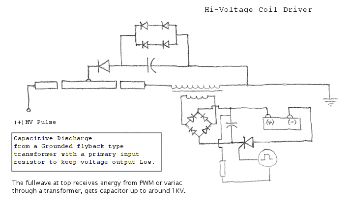
The principle appears to be to have a high voltage cap discharged trough a spark gap to the inductive load, triggered by a commutator (312), while there is a step-down transformer in series with the main (oscillating?) coil (close to the spark gap) which function is to steer a (fast switching) relay in order to dump some normal current to ground. Note that the step-down transformer is at the opposite side from the spark gap to the inductive load.
Why no details on the inductive load??
Why the dumping of current to ground??
We can find some more clues in this 2011 article, apparently a *working* prototype:
PEMM Motor Harnesses Anti-matter and Electron-Avalanche

The capacitor is pulsed by the commutator. This occurs when the rotor electromagnet is approximately two degrees or one fourth inch past the stator. At this position the electrodes align with a high voltage potential. This allows a spark to jump the gap from the cathode (negative pole) to the anode (positive pole) through atmosphere. It is during this moment that a couple of very unique phenomena take place that allow for the circuit to increase in current and voltage -- hence an increase in total power. This increase in total power (beyond what was provided by the battery) is one feature that makes this motor unique.
The motor connected to this circuit is composed of multiple stator and rotor electromagnets. No permanent magnets are used. Currently, the electromagnets use silicon steel laminations as core material. It is hoped in the future that supermalloy, permalloy, or mumetal will be used for the cores. The increased permeability of these materials could allow for even more torque to be produced in this already high torque motor.
The motor connected to this circuit is composed of multiple stator and rotor electromagnets. No permanent magnets are used. Currently, the electromagnets use silicon steel laminations as core material. It is hoped in the future that supermalloy, permalloy, or mumetal will be used for the cores. The increased permeability of these materials could allow for even more torque to be produced in this already high torque motor.
Interesting:
Silicon Steel for Laminations
Silicon Steel (Electrical Steel)
When low carbon steel is alloyed with small quantities of silicon, the added volume resistivity helps to reduce eddy current losses in the core. Silicon steels are probably of the most use to designers of motion control products where the additional cost is justified by the increased performance. These steels are available in an array of grades and thicknesses so that the material may be tailored for various applications. The added silicon has a marked impact on the life of stamping tooling, and the surface insulation selected also affects die life. Silicon steels are generally specified and selected on the basis of allowable core loss in watts/lb.
When low carbon steel is alloyed with small quantities of silicon, the added volume resistivity helps to reduce eddy current losses in the core. Silicon steels are probably of the most use to designers of motion control products where the additional cost is justified by the increased performance. These steels are available in an array of grades and thicknesses so that the material may be tailored for various applications. The added silicon has a marked impact on the life of stamping tooling, and the surface insulation selected also affects die life. Silicon steels are generally specified and selected on the basis of allowable core loss in watts/lb.
Immediately after the spark crosses the gap between electrodes, the stator and rotor electromagnets fire and produce a repulsive force. However, when the pulses cease, the magnetic field rapidly starts to collapse and reverse polarity. This is due to the concept of "Back EMF." Due to the fact both stator and electromagnets are both experiencing this effect at the same time (in phase with each other) an additional repulsive force is created. For example, if the pulse initially created a condition in which both stator and rotor electromagnet had a "north" pole facing each other after the field collapse they would both have a "south" facing pole. This effect produces additional torque the system can utilize.
All right. Now some educated guesses.
First of all, the length of the coil wire in the primary (HV side) of the step down transformer 318 is probably considerably longer than the length of the coil wire in the "inductive load".
At the moment the spark gap fires, both coils 316 and 318 are at high potential.
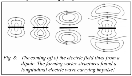
Now when the spark gap fires, you get a transient shockwave exiting both sides of the spark gap simultaneously, in the OPPOSITE direction, which propagate along the circuit, guided by the conductors, Steinmetz' transient phenomenon. In the case when you do not use a step down transformer, but you have two identical coils in series, these shockwaves are apparently capable of energizing the coils in opposite directions, because the delay along the wires and HV cap can be neglected. And if the coils are identical, the oppozing shockwaves meet nicely in the middle canceling one another out and thus restoring the balance of the aether. This process happens within the order of nanoseconds, after which the normal discharge occurs, strengthening the already energized coils.
In the case you have a single coil as inductive load, the oppozing shockwave reaches the terminal on the opposite side of the spark gap almost instantly and then the party is over. However, when you put a step down transformer with a long primary in the line, then the primary of the step down transformer acts as a delay line, so then the shockwave can energize your inductive load before the opposite shockwave reaches the other terminal of your inductive load, which it probably never does, because if the primary is indeed long enough, the shockwaves will meet somewhere within the primary of the step down transformer.
Once the coil is energized by means of both the shockwave AND the normal discharge, you get the back EMF. And that is the one that is dumped to ground using the fast switching relay, which can be a semiconductor according to the patent.



Leave a comment: