
No Back EMF in a ferromag coil
Peter, What are your thoughts on this please?
A Ferromagnetic core, torroidal wound coil, attraction, that has NO BackEMF.
JLN Labs replicates Steorn's free energy motor
Understanding the Steorn's effect by JL Naudin
Ken
-
ty
Thx, forgot about that picture. It would be nicer than the one i used for the flux leakage.
-ChrisLeave a comment:
-
Hi Chris
Everythings sounds good to me. Maybe this picture also can be helpful to you:

It is a magnetic simulation of the flux of my motor stator core. It was made by Steven (if I remember correctly) way beck when I started to build my second prototype
Thanks,
JetijsLeave a comment:
-
motor operation
Hi Everyone,
I truly believe that the following post is in the spirit of the 'electric motor secrets' discussion. I believe that in any case it would be nice to have a small summary of major concepts going into this motor, since this discussion isn't exactly brief.
Through a series of fortunate events I am currently in a position to obtain a 3-D magnetic modeling program, so I can model the motor. With this information, making a COP>1 prototype should be easier to make.
The only condition I need to meet before obtaining the program is to convince the assistant dean at my school that the design proposed in this forum is superior to other motor design available on the market, such as a switched reluctance motor.
The following is what I have been able to piece together and am planning on submitting. I would really appreciate input on what I could add and pointing out if I have mistakes.
I hope I am doing the right thing in writing this, becuase it will take up a bit of space
Basic Design:
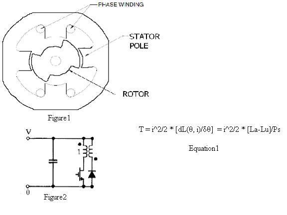
Figure 1 illustrates the stator, rotor, and coils of a basic switched reluctance motor. The stator and rotor are made of multiple layers of thin laminations of silicon steel, an iron nickel alloy. The material is chosen for its narrow hysteresis curve. Additionally, the silicon lowers the conductance, which prevents eddy currents. Eddy currents are further reduced by using laminates separated by an insulating epoxy, such as metal epoxy. The coils are of thick gauge wire, which minimize resistive losses, as well as allow for a swifter coil rise time, which will be explained in more detail later.
Basic Operation:
If the rotor in figure1 is rotating counterclockwise then the rotor is in a position for the vertical stator pole pair to be magnetized and attract the rotor in the counterclockwise direction. Electrical energy is expended in raising the magnetic energy of the stator poles and then a reduced amount of energy is used in maintaining the magnetic field.
Once the rotor pole is fully lined up with the stator, which would be the case if the rotor in figure1 was spinning clockwise with the horizontal stator pair active, the torque on the rotor goes to zero, because there is no longer a reluctance gradient. It is during this period of zero change in inductance that the energy on the coils is discharged, usually to be stored on a capacitor for later use.
There should be no more magnetic field being produced by the time the rotor is becoming unaligned from the stator, as is shown in figure1 if the rotor where moving counterclockwise from the recently discharged horizontal coils.
The rotor-stator geometry of figure1 is found in switched reluctance motors, induction motors, and pulsed DC attraction motors. There are other rotor-stator pole ratios, but they change the over all operation of the motors very little.
Basic Circuitry
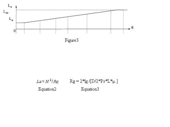
When a sensor detects that the rotor is in the correct position to be attracted, a signal is sent to the mosFET gate, and a circuit loop is completed.
If a sensor detects that the current is rising too high, a signal is sent for the voltage source to be disconnected and the mosFET gate to be turned off. The secondary coils then pick up the current, being the only path to sustain the magnetic field. The excess energy is then stored on the capacitor for later use.
This latter stage is also used when it is desired for all the energy on the coils to be dissipated.
Torque Production
Equation1 gives the expression for the torque production at a constant current. Figure3 shows how the inductance varies with the angular position, theta. From figure3 we can see that [dL(θ, i)/δθ] is a constant from the time the rotor and stator begin to align until they are fully aligned. La and Lu are the inductance of the coils when the rotor is in the aligned and unaligned positions respectively. Ps is the stator pole arc length in radians.
One way to increase torque is to increase the change in inductance occurring in rotor alignment.
Equations 2 and 3 give some insight into how this can be accomplished. N is equal the number of coil turns per stator. Rg is the reluctance of the air gap. lg is the air gap length. D is the diameter of the rotor. μ is the permeability of the free space.
Air Gap
From equation3 it is apparent that the air gap length is inversely proportional to torque production, but as the air gap becomes smaller, imbalances in air gap length and magnetic fields can lead to difficulties. A slight imbalance can cause the rotor to move in a radial direction and positive feedback occurs between the position and force until the energy on the coils is reduced. This leads to audible noise and can cause bearings to wear out. If both of the aforementioned imbalances are absent, then there will be no radial force on the rotor.
Traditionally, motors that needed more torque where simply scaled up in size, rather than investing more money in accurate machining, self-centering bearings, and precisely made coils, but the raising cost of energy is making these methods more feasible solutions to increased torque production.
Hysteresis Losses
Figure3's depiction of the inductance of a stator pole is accurate if the applied current is increasing or if it is held constant after being raised. This fact is apparent when looking at the hysteresis curve shown below.
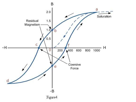
The inductance of a coil is a function of the slope of the hysteresis curve. For a soft ferromagnet, like silicon steel, the residual magnetization and coersivity are both very low, nevertheless, it is ideal to minimize the changes in the applied field, as in delivering isolated pulses of current.
An interesting point to note is that the torque or mechanical energy production is proportional to current squared while the electrical power is equal to voltage times current which is only related to current in the first power. It seems reasonable to want to set in off in the direction of maximum current.
Saturation
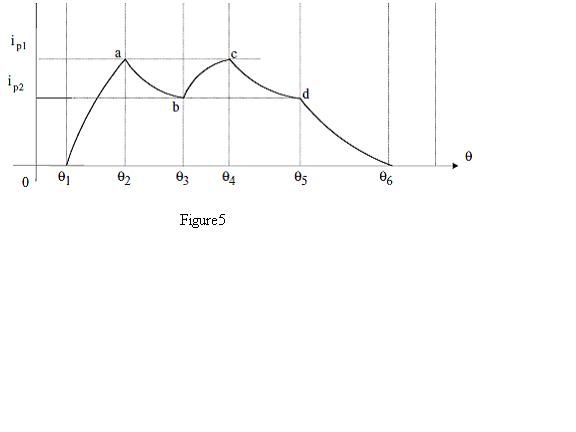
There is a limit to how much current can be put through a motor. When the applied field is increased beyond the materials saturation point, an increase in applied field will not result in an increase in torque, which can be very bad, since, as the inductance drops, the rate of current growth increases and a lot of energy can be dissipated quickly.
In order to avoid saturation, switched reluctance motors make use of the secondary coils and discharge the current, as seen in figure5. Figure5 leads to what is known as a torque ripple, which is the reduction in torque due to hysteresis losses.
Stray flux losses
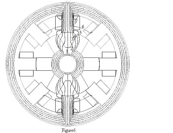
Figure6 illustrates possible pathways for the flux lines, for a 8-stator 6-rotor motor when the rotor and stator are not aligned. Ideally all flux would path through path 4 or 5, the shortest possible air gap, but when the material reaches saturation in some segment that portion acts as if it were simply air, so the flux will take one of the other possible paths open to it, but not one that contributes to torque production.
The more alignment that occurs between the rotor and stator, the less stray flux lines will arise. Additionally, the more alignment means that the material can handle more current before saturation occurs.
Lenz's Law
Raising the current on the coils requires more energy than simply maintaining the current. A steady current only has the resistance of the wires to hold it back, which is less than an ohm, so total electrical energy dissipation is quite low.
The energy expended in raising the coil current is larger than the resistive losses, but the extra energy put into raising the current is not wasted, like resistive losses. The energy put into raising the current is stored in the magnetic field.
The percentage of energy recovery possible from the coils diminishes with the amount of rotor-stator alignment. With a pulsed input, the total angle of rotation which occurs is minimal.
There are other methods of increasing the rise time of the coils, rather than simply increasing the applied voltage. If the charging coil's inductance is decreased, it is able to rise faster. This can be accomplished by winding the charging coils out of two strands of wire that are wound at the same time. The ends are tide together, and you have what is known as a bifilar coil. The result is you have two inductors in parallel, which add inversely, hence a reduced equivalent inductance.
For the recovery coils, one can make it out of a single strand, of a smaller gauge and more turns. The result is an increased inductance, which makes the decay time longer, which may prove to compensate for the added resistive losses.
Swiftly changing currents can result in skin effect and proximity effect in wires. It may prove to be worth while to utilize Litz wire for the coils.
Conclusion
It has been the author's intent to simply provide a qualitative investigation into electric motor operation and point out that there is a window for improvement. Just how much improvement is available can be realize upon further investigation with a 3-D magnetic modeling programLeave a comment:
-
Hello Turion,Originally posted by Turion View Post
Well, an idea came to me to combine an attraction motor with Joseph Newman's principles. Joseph Newman says a lot of things, but the thing that interested me, and I verified it experimentally, was the fact that the magnetic field strength remains the same for the same wire by increasing the wire length, thus consuming less current for the same magnetic power output.
Some argue that the time constant increases by increasing the wire length as the inductance increases, but I tried to show here (http://www.energeticforum.com/renewa...nciples-3.html) that this is not the case.
The problem with Newman's design is that he uses a magnet as the rotor and when it turns, it induces a very strong back-emf, because of the long wire length, limiting the motor's speed of operation, thus lowering the efficiency of the motor. But Dr Lindemann's design which uses a piece of Iron, as the rotor has not got this problem.
Anyway, some idea to experiment with.
EliasLeave a comment:
-
"Please do not think you can just build a motor and have it work perfectly. You can see what Jetijs and Eric are going through. If you build something before you do a complete engineering study of the design, you are building a prototype of an experimental motor. In other words, you are just running an EXPERIMENT.
I appreciate your interest, but in all honesty, this project simply isn't far enough along for you to do what you want to do."
Peter,
Believe me, I have read every word of this thread, have watched your video several times, and understand that what I would be building would be nothing more than an experimental model. All I am looking for is as much information a I can get from those who have gone before so that I can take advantage of their experience. I do not know everything that Eric and Jetijs have gone through except for what has been posted here. From their experiences I have made tons of notes regarding the steps they took, their designs, and the materials and parts they used, and I intend to have a motor built that incorporates the best information available to me. I was just wondering if there was anything else you would suggest in addition to what has been presented at this site. Otherwise, I am going to have my motor built and then let the fun of trying to get it to do what it is supposed to do begin! I am used to beating my head against the wall, only I am one of those guys who doesn't give up until the wall is reduced to powder regardless of the consequences to my head!Leave a comment:
-
thanks!
hi!Originally posted by Peter Lindemann View Post
thanks! nice to hear from you, hope your thanksgiving went well. sorry the econnomy is hitting you as well. its taken its toll on me (cut hours at work) and (and this is good news) i am gonna be a dad! so my project got shelved again but i will be back on it hear in a week or two. i should have posted more of my notes i have a whole mess of notes i have yet to post. in these tests i found 300hms to work well for a 12 to 30volt supply. in my earlier motors i allready new that 100 to 200ohms was too low, the resistors would get hot! with this current circuit and the new smaller gauge winding the mjl trannys run nice and cool... lol i was having a brain fart trying to figure out why you would recomend connecting the base to the collector i tried removing the resistors before and blew a tranny! then (duh!) i realized that by doing that i would be placing the motor coils between the + source and the base effectivly giving me a low ohms resistor between those to points. (lol why didnt i see that!) so i will try it, but unless there is a difference in using a coil wound resistor (the motor coil in this case) as opposed to a semiconductor type resistor i think the 8 ohms in the motor coil will still be way too low eather causing too much heat in the tranny or blowing out all together. as for sparking i dont have any sparking when i use the commutator
to control the base of the transistor. i only had sparking when trying to remove the tranny from the circuit and run all the power through the commutator!! i have yet to find a good mechanical solution to that. i have been trying to read up on sparksnubber concepts but i have yet to find good reference materiel on how to design a good snubber circuit specific for this type of application.
when i have some time i will post some more notes, hope all goes well with you and your work.
cheers!
EricLeave a comment:
-
Hi all,
It's been a while since my last post in this thread. I have nothing new to tell yet, because as Peter said, I am busy with other and not so interesting things right now. Anyway, I wanted to tell that last week I held a lecture about Bedini devices and Peters attraction motors at local particle physics institute. They organize seminars each month and many other enthusiasts like me visit those seminars. The main topics there is renewable energy. Anyway, I shared what I know and demonstrated my attraction motor. I used V2.0 motor to show the principles, I made everything so that I could put the inductive spikes to the front side capacitor using a switch when the motor was running. At 12v it rotated at about 3500RPM, was loud and consumed 2.4A of current. When I flipped the switch, the current consumption suddenly dropped to 1.4A, the motor became much quieter and the RPM's increased noticeably. That was a real eye opener for many of the people there, everyone was very interested. I will make a short video that demonstrated this, so I can promote this technology further and maybe someone with more free time and resources will be able to bring this thing to the next level.
Also just then I realized why this current waveform of V2.0 motor looks like it does:

This image shows the short current pulses that fill the whole 70 degree attraction window, they all are equal in duration, but nevertheless each next pulse gets shorter and shorter in amplitude. This is because already at air gaps of 0.13mm the varying core inductance trend starts to show itself and it gets even more obvious if the air gaps are even smaller, like this waveform with 0.08mm air gap:

All this need to be taken into account when building such motors. I should have realized this earlier. But what can you do, you never stop learning
I hope this helps someone.

JetijsLeave a comment:
-
Eric, Awesome Work
Eric,
Glad to see you are at it again!! Here are a couple of ideas that may help. You might try using lower value resistors in your commutator section, like 220 ohm or even 100 ohm. You could also try to just connect the Collector to the Base through the commutator contact, with no resistors at all, as a simple "forward bias" arrangement. What you want to watch out for is protecting the Base of the transistor from the inductive spike. Another simple method is to use the H11D1 opto-isolator. The commutator can be used to simply turn on the LED side and the output can be used to Darlington the transistor on.
The commutator won't spark if there is very little current and no inductance in the circuit being switched. When the transistors are slammed on and off quickly, they shouldn't heat up much, at all. Still, you might consider putting heat sinks on them.
Keep up the great work.
PeterLeave a comment:
-
No Final Design
Dear Turion,Originally posted by Turion View Post
Thank you for your enthusiasm for this project. No final designs have been developed for this motor concept, for a number of reasons.
First, this is a learning forum, where people can learn about the "attraction motor" process and combine that with electrical recovery.
Second, this is a long thread, and early on I told people that the BEST designs would not be a "variable reluctance" topology, like we are working with here, but a "constant reluctance" topology. This sort of design would allow electrical recovery to approach 95% while producing high torque.
Third, like Jetijs, I have been deeply effected by the "economic downturn" and have not been able to put any time into this project (or any other project) since the summer of 2008.
Fourth, I have decided to develop these designs in 3D simulators from now on, so all of the mistakes can be worked out quickly, and cheaply, and the specifications for a real, working motor with high COP can be finalized. But right now, I am 100% busy, working to make a living.
Please do not think you can just build a motor and have it work perfectly. You can see what Jetijs and Eric are going through. If you build something before you do a complete engineering study of the design, you are building a prototype of an experimental motor. In other words, you are just running an EXPERIMENT.
I appreciate your interest, but in all honesty, this project simply isn't far enough along for you to do what you want to do.
PeterLeave a comment:
-
Motor design
My next goal is then to contact ANOTHER company who builds plastic sleeves that could be wound in my shop and slipped onto the arms of the stator, so that I can experiment with different winding designs, lengths, numbers of wires, etc. But the first step is the motor case, stator and rotor. If the housing should be made of anything specific or the bearings, please let me know. I want this to be the "perfect" motor so that we have eliminated as many variables as possible before we start with the fun!
I know you are posting on other threads, like the rotoverter thread, so I hope you will have time to help me in this replication project. I think it will be worth your while since there will be two of us using exactly the same motor and if others are interested in jumping in, I can get a cost breakdown for them and we could all start at the same time. What do you think?Leave a comment:
-
Motor design
Peter,
I live in San Jose, CA. Have access to custom motor fabrication facility. If you give me the specs and design info, I will have two custom motors built, one for a friend in Brazil to duplicate my replication efforts. Are the designs posted here as good as it gets, angle of stator faces (70 degrees), shape of rotor and stator, air gap (.08 or less per side), material of rotor and stator (siicon steel laminate .35mm per plate or less)? Is there anything else I need to know before I have this done? I only want to do this once since I am on limited budget. I will hen have the contact and cost info available for anyone else who wants to replicate. I have seen some discussions of the rotor made of a permanent magnet. Would you advise this? I am having the case, rotor and stator and bearings done, but will do the winding myself to save cost. Also, I want to KNOW how many winds there are, the direction, how they are twisted, etc.Leave a comment:
-
EFV DVD Part 14
Has anyone seen the EFV Part 14 DVD about the Lockridge device?
I am thinking about buying the DVD but I want to know if it actually talks about and/or shows how the device is made?
I hope it is ok to ask this question here? If not feel free to delete it....:-)
Be happy....
TjLeave a comment:
-
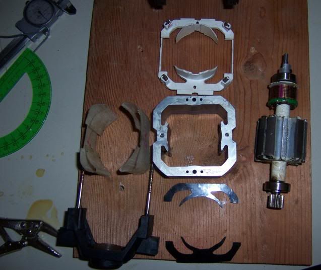
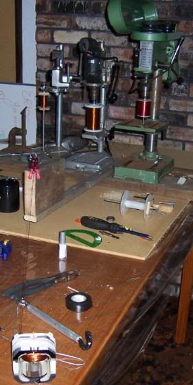
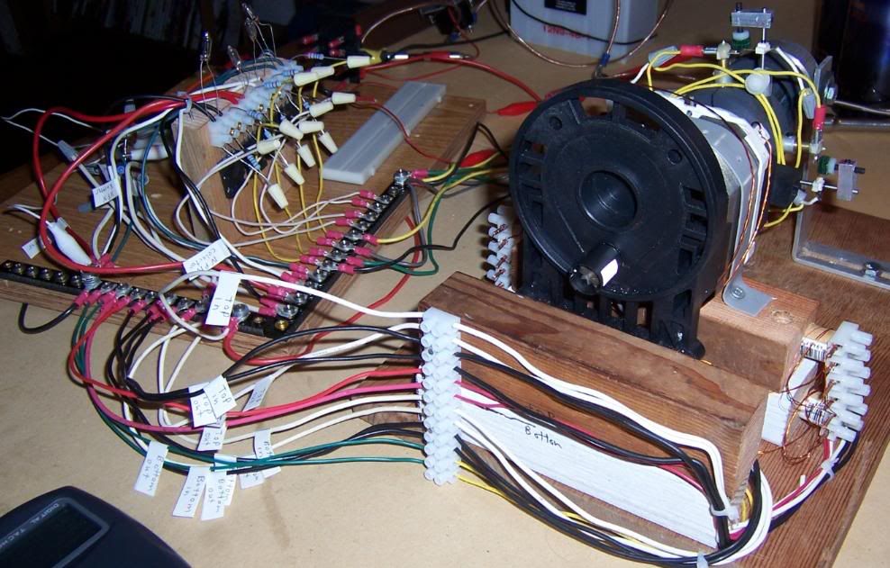
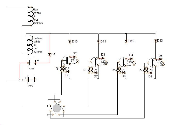
ok here at last is a video some more pictures and notes for the first test run of my third motor the coils consist of 2 power wires 26awg about 90 feet long measureing at about 4ohms each. when i rewound the motor i decided i wanted to play with a passive sense wire as well so there is a third winding at 32 awg 90ft and reads about 16ohms each.
the circuit in the video is only using one power winding so its running at half strength right now. its using the top and borom poles wound in series giving a total of 8 ohms. in this run i have set up 1 transistor for each switch and added some extra diodes so i could use my oscope to adjust the green felt vibration dampers. this gives me a more solid on time. after that i just decided to film my vid before going back to 4 switches turning on 1 transistor.
i wish to start with the most basic circuit, log some notes and add changes/advancements 1 step at a time. the circuit i am building is very plug and play so i can alter the circuit very easily.
here is here are some pics on constructing the coils
here is a circuit diagram
and here are some log notes of the first run
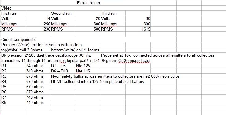
the only reason that 2 of the transistors have different resistors than the other 2 is i could find enough of the same ohms in my supply at the time.
here is the test video. its a little rough, my fancier hd camera quit working and wasted a lot of my time so i am using a video feature on a digital still camera i have. it outputs .mov files and i am trying out the avs4you software video converter before purchasing it if anyone can recomend a better package i am all ears.
YouTube - first video test of version 3 motor
cheers!
EricLeave a comment:
-
Sorry, no progress yet. Both motors are sitting on a shelf and waiting for better days I am too busy with other things right now.
Leave a comment:

Leave a comment: