
Nice test rig, simple but very functional.
what battery are you using? it may be that such a small battery is current limiting the motor, if so you could run it on a lower voltage and get the same performance ie less power in and same mechanical power out.
-
sound analysis
since i had no means of measuring rpm i was creating a sound signal off the flattenned end of the shaft that could be analysed.Originally posted by penno64 View Post
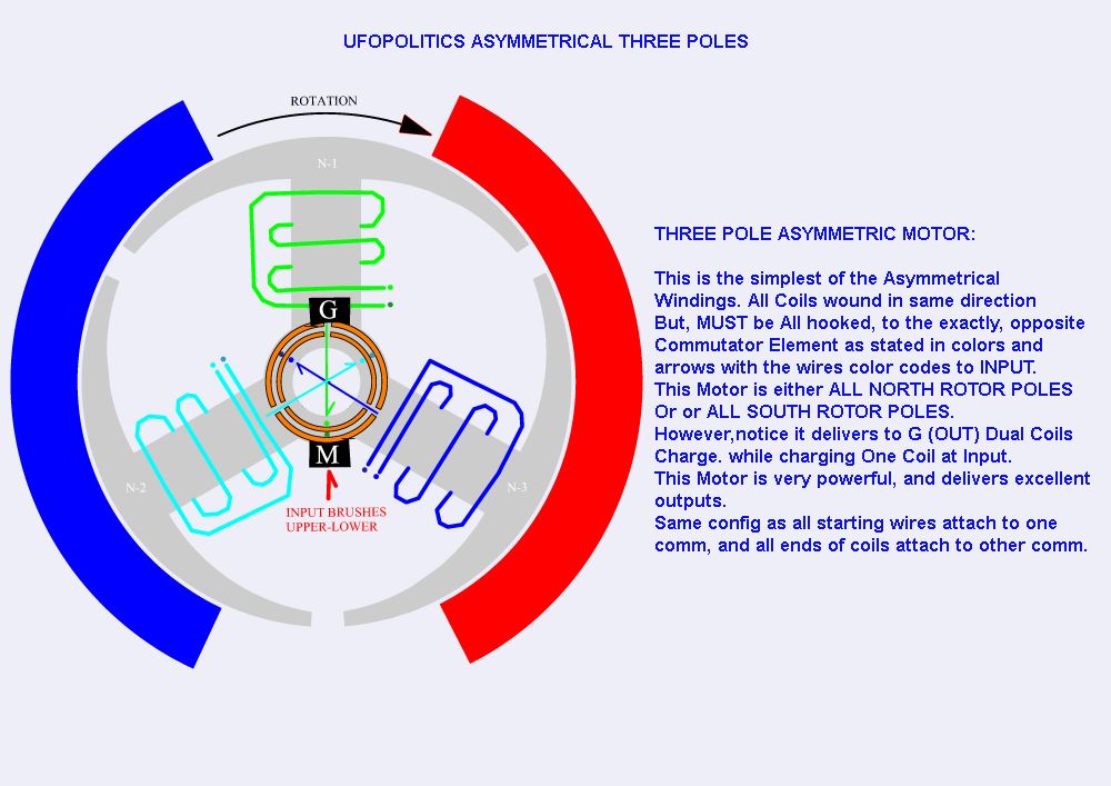
the switches allow switching between standard symmetrical design and Ufopolitics asymmetrical design....and using the same components is aimed to better analyse his design vs standard...unfortunately i lack the necessary equipment edit:skills or knowledge ;-) /edit to do a proper job.Last edited by s e t h; 09-20-2012, 08:01 PM.Leave a comment:
-
Hi Seth,
What is it that you are moving/poking at with the food skewer?
Regards, PennoLeave a comment:
-
please excuse me butting in...
BEMF solution may lie in investigating holding it temporarily and then releasing it when it will mimic a powered cycle.
please note the bottom dual asymmetrical design is mine and not Ufolpolitics' and does not output as well as the standard asymmetrical design as it appears the BEMF trying to escape through the generator brushes directly opposes and cancels the induced current as the coil passes the magnet.
the pure asymmetrical design does however have measurable flow out the generator brushes.
>video of operation<



Leave a comment:
-
I cant wait till I get the video
Hi Peter, my own experiments lead me to all the conclusions you have posted here and more but I have not as yet been able to limit the BEMF enough, still working on it.
It is true, it does work on simulators but on the ones I have it does not simulate iron losses.
I am not interested in NDA's as I want the information out on how to do it. To be truthful even when I tell people how to do it they do not understand it hehe One thing you did not mention is three devices on one iron core giving three functions and only one loss. This bumps the efficiency up.Leave a comment:
-
Everything is Revealed
Hi Guys,
Thanks for keeping this thread alive. Back in September of 2010, in this thread, I posted the following information:
The DVD (Electric Motor Secrets) was produced 3.5 years ago, and since that time I have been working with a number of people on this concept. We have run hundreds of computer simulations on the method and developed very advanced designs, which I am not free to discuss here, because we have all signed NDAs.
I can tell you that the ideal motor, based on these principles, has a number of characteristics. These are:
1) The coil impedance of the system is quite low, to allow rapid charge and discharge of the coils.
2) The inductance changes very little through the power stroke, to maximize electrical recovery. The way this is accomplished, I cannot discuss.
3) The reluctance of the total magnetic circuit changes very little through the power stroke, as well.
4) Input supply voltage is kept to the lowest value possible by limiting BEMF in the input coils. The methods used to accomplish this, I cannot discuss.
5) Mechanical power production is managed by optimizing the timing, the size of the air-gap, and the total coercive force of the magnetic field across the air-gap, measured in Oersteds.
6) Capacitors are used in the electrical recovery circuitry.
Well, I am happy to announce today, that Dave Squires is the main person I was referring to here, and all of the issues I said I could not discuss are COMPLETELY REVEALED in Dave's lecture titled Advanced Motor Secrets from the Summer Conference.
If you ever wanted to understand all of this, just click HERE.
Best regards,
PeterLeave a comment:
-
Hi guys!
Here's the next step on my "Flux transfer generator" .
Four n52 magnets 1" x 1/2" thick all same polarity on the bar shaped rotor .
The stator has 3 coils.
When the rotor is outside the stator, it wants to stick to everything but when inside the stator, it can be turned easily.
Just like the previous one, it behaves as expected and barely decreases when shorted.
The coils are too small (130 turns each) so I need to change the stator size
to produce more voltage.
I used a dishwasher motor ,($9.00 at a surplus store) ,and modified it.
RobertLast edited by Robert49; 12-30-2012, 01:09 AM.Leave a comment:
-
Thanks Harvey!Originally posted by Harvey View Post
I'm happy to see someone noticed.
The arrangement of the spring may not be right but the main idea got through.
I'm working on my "Flux transfer generator" right now. Still waiting for the modified rotor but I already modified the stator. I should have pictures of the setup in a few days.
Fun to experiment!
RobertLeave a comment:
-
Hi Robert,Originally posted by Robert49 View Post
I just wanted to commend you for your application of the parallel slots to achieve pulse width adjustment in this speed control design. It is a very subtle thing which is a bit counter intuitive where the same dimensioned slot can provide such a beautiful analog adjustment relative to the surface speed of the disc even though the angular velocity is identical for all radials.

Leave a comment:
-
Hi Donald.Originally posted by Donald Haas View Post
Yes the neo magnets are perpendicular to the soft iron cores and all the same polarity but not going through, just sitting on the surface. This way the iron cores only have one polarity.
The magnetic circuit is not broken but transfered from one side of the rotor to the other 16 times per rotation, thus expanding the magnetic field alternately to either side.This setup has very little drag.
I have already designed a better way to do it with a very small air gap ,even less drag and more output.(hopefully)
Fun to experiment!
Robert
Leave a comment:
-
flux gen
Hi Robert,
It looks to me like you have neo cylinder mags going through the middle of the coil(s) core at a perpendicular angle.
Am I seeing this right?
I see the soft iron rotor pieces are alternately arranged to break the magnetic circuit 12 times per rev. Is this correct?
Havn't seen this kind of setup before.
Please reduce my ignorance as needed.
donaldLeave a comment:
-
Ok Robert, thanks. It is a good sign the speed barely decreases when you short the coils i.e. you load the coils with their own 'inner' impedance.
Thanks and keep up good work.
GyulaLeave a comment:
-
Hi Gyula.Originally posted by gyula View Post
I just made this last friday from parts of another project.
The present setup is not very efficient but it does behave as I expected and prooves my theory.
My next setup will be more compact and more powerfull but I have four ongoing projects and very little time to work on them so keep looking me up.
Fun to experiment!
Robert
Leave a comment:
-
Hi Robert,
May I ask on output power measurements vs input in case of the flux transfer generator?
Thanks, GyulaLeave a comment:
Leave a comment: