-
Speeding up under load at 2800 RPM or less is NOT just dependent on number of strands on the coil and how many you put in series. The other variables are the length of the strands, the size of the wire, the number of magnets on your rotor as well as the STRENGTH of those magnets. Also the distance between the rotor magnet and the coils. Unless all these things are exactly the same as my machine, your results will be different. -
Hello Mr. Dave
It is nice to hear from you, and the progress and achievements with your generator, the new challenges you are facing.
Good blessings for your driver to recover and continue supporting you.
All your recommendations illustrate the great progress you have made with your project. And that they also help us, it saves us a lot of research work since you have achieved it, and they also guide us to make a replica of your project.
In one of his statements he also commented this:
motor-generators / page30 # 449
12-22-2019, 02:18 PM
The second, and the MOST IMPORTANT CHANGE is the coil. My original coil had three 1000 ft. Wires. They would accelerate under load at 2800 RPM. At RPM LESS than that, they act like regular coils. When I went to 6 wires each 500 feet long, with two connected in series, I saw the required RPM drop. When I went to the 12-wire coil, it dropped to 1140 or POSSIBLY LESS. The engine my driver is currently using runs on its 1140 RPM batteries and is accelerating under load. We have not tested it at low revs.
I have built the 12-wire coil, connect them in 4-wire series, 3 in parallel. By your comment you should accelerate to 1140 rpm, it means you can accelerate to that speed and 2800 rpm.
I am awaiting speed control for testing.
What he says about the repulsor magnet to eliminate the magnetic drag nucleo-magnet, if in fact I also tried smaller magnets and could not be repulsed.
The repulsor magnet also helps to give an inertia to the spin of the extra rotor, a magnetic stop (NN) is also given when returning to meet the other magnet, the inertia and the attraction of the coil core with its magnet make that stop magnetic is overcome, and thus the repulsion (NN) occurs with an extra inertia to the rotation of the rotor.
So it is required to give an adjustment between the suppressor magnets, just in the repulsion attraction between magnets, that adjusts to the attraction of the coil core and the generator magnet.
This aspect of the magnetic drag suppressor magnet is very important as Mr. Dave has commented, it helps us lower the motor's current draw, and much more the more coils we connect to the generator. I remember how he comments when he burned several motors when he did not have the magnetic suppression of the drag, and brilliantly found a solution with the guide of the patent that mentions.
Thank you for your contributions.Leave a comment:
-
The reason for the 36 strand coil is simple. You should know exactly the length if each strand if they are the same. Put all 36 strands in series. Will the motor speed up under load? Probably. Now put 18 strands in series and a second group of 18 strands in series. Will the motor speed up under load? If it DOES, put 12 strands in series and then two more groups of 12 strands in series. Will the motor speed up under load? If it DOES, put 9 strands in series, and three more groups of 9 strands. Will it speed up still? If so, put 6 strands in series. Then five more groups of six. If it speeds up, try 3 strands. If it speeds up, try 2. At SOME point it will NOT speed up under load. This gives you the minimum number of strands of the length you are using to achieve what you want. Or start with two strands and work your way UP instead of down. Once you know the minimum number of strands, you can figure out the combination that will give you what you want. As many strands as possible in parallel gives you lower voltage but more amps. Adding to the LENGTH of a working minimum gives you more voltage but lower amps.
if I have a100 strand coil and all the strands are in series so it speeds up under load, my voltage output will be high, but my amperage output so LOW that it won’t run anything, and the voltage will probably be too high to run anything anyway. Understanding how to control the output of your coil is the only way to get its output in a range where it can be manipulated EASILY to run the motor that is turning the generator.
As for my house remodel. I am shooting a video today to show my sons the progress and what still has to be done. I will post the YouTube link here and you can watch it if you are interested.Last edited by Turion; 04-23-2020, 03:57 PM.Leave a comment:
-
That is very interesting for me as I am sure you are well aware. Others may be bored by such details. As you know Jordan an I have that other Madmack platform where we learned a great deal about repulsion magnets Changing sizes and using shielding on the bigger ones to control the peripheral amounts so as to balance TDC repulsion with it's adjacent field with respect to the incoming. I will make a note of your comment and ponder.Originally posted by Turion View Post
Yes on very large machines precision work could pay off handsomely. However those who are able to produce a rotor that does not wobble or have end play might be able to mount coils free hand around the perimeter. Moving coil in closer seems like would get your machines even hotter and require you to shut down much sooner between runs. No?
The other info on arranging so many strands in a variety of ways is still just out of reach as to why but remembered that you said this before as I went into brain freeze. Each time I reconsider, I come closer to the prospect and that one is pretty important right now as we are almost at that place where those kinds of tests could be made on our rig. Thanks again Dave.
Tell Grayland I said OMG and tell him I will pray for him now that I know he is in stitches. He probably works so hard and in the excitement over does it. Hope he gets better and you also are doing well. Concrete work is a man's work so I am confident you are great. Next time talk about the progress on your 2 homes.Last edited by BroMikey; 04-23-2020, 11:40 AM.Leave a comment:
-
Nice progresss Bro. It's looking good.
My Machinist, Greyland, ended up in the hospital with a blood clot that caused loss of use of his right arm. He is out of hospital, on blood thinner, and has to do some therapy, but had the generator back together and ready to do some testing before he had this episode, so as soon as he is allowed to get back at it, you will probably get some more video. Likely a couple days. He can't work, so is spending all his time on THIS project. Excuses, excuses.
A couple comments:
A 50 strand coil allows FIVE possible test combinations, because 50 is divisible by FIVE numbers
1
2
5
10
25
So you can put 2, 5, 10 or 25 strands in series, and use ALL the strands on your coil to make equal length strands.
I have, for quite a while, recommended a 12 strand coil which has SIX test options
1
2
3
4
6
12
A 3 1/2" x 3" bobbin will hold 36 strands of #23 each 85' long. With a 36 strand coil, which is MUCH easier to work with (than 50) you have MORE test combination options, which is why I said that 36 strands is the BEST coil with a REASONABLE number of strands because it has EIGHT test options
1
2
3
4
6
9
12
18
The more wires you have in parallel, the greater your AMP output. The more wires in series, the greater your VOLTAGE output.Once you know the minimum number of wires you MUST have in series to get the "freewheeling" condition, you can decide whether to go for more amps or more voltage. Different numbers of wires connected in series will help you determine the FEWEST wires it takes you in series with YOUR rotor with YOUR magnets and YOUR motor rpm to get the freewheeling condition. With any luck, it will be far less than 36 strands in series.
I started with 3 strands each 1,000 feet long, and with my rotor I had to run at 2800 RPM to get the freewheeling condition. With only 3 stands wound in parallel and connected in series (each 255 feet long) or 765 feet in TOTAL length, (four of these on the coil) I was able to bring the RPM down to less than 2,000 and STILL get the freewheeling condition because the CAPACITY of the coil increased with the strands wound in parallel and connected in series. The wire length was SHORTER, (765 feet instead of 1,000) but the capacity GREATER. Learning these things is why TESTING and BUILDING YOUR OWN MACHINE is so important.
I will mention one more thing about the generator. Bro Mikey is correct, you can put one together in your garage that will PROVE to you that all this is for REAL, but you will NEVER see the real potential until you build one with close machine tolerances. Getting a machinist involved has sent my learning curve through the roof, and I have tried to pass this info on to those who will listen. Greyland moved the coil holders in .005 closer to the rotor on each side of the rotor, and the 3/4" by 1/2" thick N52 neos that we were using as opposition magnets were NOT able to neutralize the attraction of the magnets on the rotor to the iron cores of the coils, even though this moved them in closer to the rotor as well. That blew me away. This tells me that the attraction of the magnets to iron is STRONGER than the repulsion to another magnet, or at least to a magnet the size of the ones I am using. I would NOT have believed that if Greyland hadn't seen it and sent me the video. We would have to tear the machine down and put in THICKER opposition magnets, which would require a bunch of other changes, with NO assurances that the thicker magnets would solve the problem. So he moved the coil mounts back out to where they were. But it DOES give us more information that will be used on the NEXT version of the machine to improve its output. We will DEFINITELY try thicker opposition magnets because that SHOULD work according to the math BUT, I believe it when I see it on the bench. Nothing about this stuff is as cut and dried as some folks would have you believe. The output of the coils DID increase SIGNIFICANTLY with the change in coil holder position. Is that important to know? Dang right it is! We still have 1/16" spacing on each side of the rotor. A MORE precision build could cut that more than 50% and what that will do to the power output I can't say. But that would mean the surfaces of the coil holder have to be machined smooth and everything perfectly aligned. Cannot do that in a garage. Or at least I CAN'T. The rotor would have to be mounted PERFECTLY on the shaft to assure NO rotor wobble. I don't think we have any NOW, but there can't be any at all with those kind of tolerances,Leave a comment:
-
Very good demonstration of your project BroMikey, so we can study and if we want to build a replica, we can do it, and it's good that you keep looking, experimenting, innovating, building and sharing your project, thank you.
I want to comment that the speed control arrived, but it was returned to the delivery office, according to them I was not at home, they will bring it back, with the speed control I will be able to regulate the rpm of the motor-generator, as well perform the necessary tests.
I really appreciate all those who work and share their projects, those who seek improvements in energy generation, it is not an easy job, it takes time, dedication, effort, material and economic resources, but you have the passion to continue with impetus and dedication to study, to discover.Leave a comment:
-
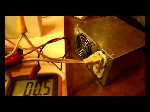
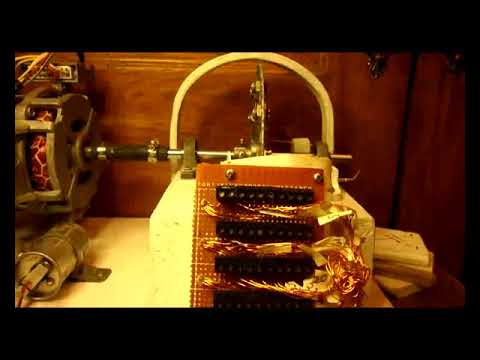
Soon the proof of concept will be delivered, in this lifetime. ReGenX style generator.
Leave a comment:
-
31vac X 450ma = 14watts drive power needed to pull the rotor. I ran it down slower than 1750rpm and you begin to hear the motor humming which signals a slightly inefficient operation but not bad. I went to 22vac X .45 amps or 450ma. The amps stay the same down to 16-18vac and the speed can be dropped some.
This rotor is smooth, this is what I was wondering, so mission accomplished. As I lower the volts way down to as low as 10vac the amps climbed to .68 or 680ma this is 10v X .68 = 6.8watts of drive energy and the rotor was way slower say 600rpm (Guessing) this is where you hear humming. So I went up to 18vac the amps were .45a all the way to 22vac X .45a and the rpm was just under full speed around 1500 rpm, no humming sound.
This is the first step to establish a baseline input power requirement for turning the rotor. The arrangement allows careful monitoring to changes in amp draw. That is what you need. For instance you would not use a full 1/4hp motor to drive the rotor because you would be unable to measure small changes to the system. This is approx 1/50th HP. 750watts being a full 1 horse power divided by the 14 watts I need.
Remember John Bedini's 1 watt challenge? Maybe I'll call this the 25 watt challenge.

 Last edited by BroMikey; 04-21-2020, 11:52 AM.
Leave a comment:
-
Thanks Alex, Jordan and I have been working on it today. Mounting and alignment. Protective cover and frames to hold it going on now. Slow motor makes this project much safer for a beginner. Teaches safety. Slow motor (1750) no tachometer needed, large oversize coil (50) lower RPM operation plus 10 magnet stations also further reducing the need for extreme speeds. Formulating now on adjusters for counter opposing magnets, fine threads. Once the opposition magnets are in place (one on each side pushing)
I will be confident it will be time to test the rotor at speed. Mounting first.Last edited by BroMikey; 04-21-2020, 11:49 AM.Leave a comment:
-
I also want to comment that I have been working all these days, on the generator project. How much work, burn various power sources I have to fix them, I maintained the batteries for 36 volts.
Perform tests with other coils, they accelerate in a short circuit, I could not find the optimal speed all this I will detail in another forum link.
I started to improve some bedini engines that I had abandoned, well one keeps trying to find the philosopher's stoneLeave a comment:
-
Good that you are working,BroMikey. it is a lot of work thank you for presenting us your engines Thank you very much, there are always many tests.
You have studied Thane's projects for several years, it is good that you make a replica to see his proposalsLeave a comment:
-
Of course the goal is to keep the drive current down with the core in place the same as just driving the rotor all by itself. This will happen. This means 10-20watts max drive input (guessing) we shall soon see. The coil will produce 110vac easily and the wire can handle a max rating of 450 ma. It will probably deliver somewhere under that but I am only guessing, We will see. Let's say it produces 200ma only 110vac X 200ma = 22watts and this is for only half the coils. Double that. I would expect 50 watts myself minimum. If not I will see if the bigger magnets will bring this up. Steady at it now because Jordan's school is going to let out in May and I want it generating for him well before this.Leave a comment:
-
Testing in progress. Spun up the rotor with cordless drill to 300rpm with only 4 magnets on the rotor with c core in place. It had drag there is no doubt. Output volts 10vac so probably at 6X faster (1750) going to be 60-70vac. Switched to 10 magnets on the rotor. Indicated all 10 magnets, very happy with that. Lots and lots of drag on the cordless drill running only at 225-250prm guessing, very much slowed down my cordless, much more with 10 magnets, heavy cogging, produced 20vac so maybe 140-150vac at speed (1750) guessing again. We shall see. Cancellation magnets will be a must to keep drive motor amps lowest. Like I said this is 30 strands of 72' each or 2160' of coil. Still working on many things to mount the motor, brackets all done, just mounting. I am sure it will speed up a great deal upon loading that I do know.
Last edited by BroMikey; 04-19-2020, 12:34 PM.
Like I said this is 30 strands of 72' each or 2160' of coil. Still working on many things to mount the motor, brackets all done, just mounting. I am sure it will speed up a great deal upon loading that I do know.
Last edited by BroMikey; 04-19-2020, 12:34 PM.Leave a comment:
-
30 coils done = 69 ohms = 30 X 72' = 2160' These 30 coils or strands are all connected in series for the moment. 20 more to go.
Leave a comment:
This forum is preserved as a permanent archive. The community continues at eMedia Press.
- If this is your first visit, be sure to check out the FAQ by clicking the link above. You may have to register before you can post: click the register link above to proceed. To start viewing messages, select the forum that you want to visit from the selection below.

Leave a comment: