Announcement

Collapse
No announcement yet.

Motor Generators

Collapse
X
 
  • Filter
  • Time
  • Show
Clear All
new posts

  • alexelectric
    replied
    Originally posted by Turion View Post

    As to MY setup...
    In the experiments I have done over the years, I have seen the differences between open voltage and voltage across the load, and I know THESE coils produced 260V AC open voltage and between 120-130V AC across the load on the OLD machine. All I can figure is that I need to file on the cores more to get them all the way into the holes they fit in. I didn't realize it was going to hurt quite so much to file these.


    Regards Mr Dave
    From your comment that your previous machine gave you more voltage in the coils, you know in what conditions and configuration you used previously, there are things that I will mention and you already know them and you know them, the magnetism of the magnet, the approach of the core and the magnet , you change to other magnets.

    His old machine gave him very good results, and it didn't matter if it worked for about 10 minutes or 15 minutes, it gave him the voltage, the rotor didn't brake, he made the motor consume less with the neutralization magnets.

    He commented that his old machine, the problem it presented was the adjustment of the neutralization magnets, in my machine I also had that problem, the magnets vibrated, until I adjusted it and held it well and it improved.

    His interest in improving things made him make his new prototype, okay, one can think and suggest some things, I wonder if he would have made the new machine the same as the old one, but with the support material used in this new machine .

    Your new machine has more magnets, it is supposed to turn at rpm, etc, you have a good project, you have advanced a lot, you have documented a lot, it showed that the coil does not hold the rotor, that you can also reduce the consumption of the drive motor.

    Your generation proposal will be studied by those who are interested in new things, and it will be improved, every prototype is subject to study and improvement, and in particular I consider it so, and as you comment Mr. Dave, since you show your equipment working He leaves it to those who want to continue improving it.

    I always appreciate your contributions.

    Leave a comment:


  • BroMikey
    replied
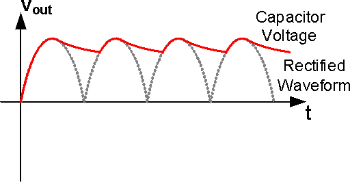
    Simple rectification facts. Caps can adjust your voltage output for a given number of amps on the load.

    Leave a comment:


  • BroMikey
    replied
    Yes, you can tell if a coil is in all of the way by sticking an empty spool in a hole and then judge whether the spacer is half cocked or out further than it should be.

    On rectification, here is an example of what's on the market. Notice all of the caps for HF system is 20amp
    A couple of these will handle 1.5 amps 250v @2200uf = $6 bucks each, poor boys can't afford it.

    https://www.ebay.com/itm/39382450159...8AAOSw5Plhx-7X

    Last edited by BroMikey; 01-23-2022, 05:59 PM.

    Leave a comment:


  • Turion
    replied
    The Variac put out 110V AC when turned all the way up.
    When turned all the way up and rectified, it only put out 110V DC.
    So between conversion losses and the differences between AC and DC, according to the Demo 124V AC converts to 110V DC. That's a ig difference.

    As to MY setup...
    In the experiments I have done over the years, I have seen the differences between open voltage and voltage across the load, and I know THESE coils produced 260V AC open voltage and between 120-130V AC across the load on the OLD machine. All I can figure is that I need to file on the cores more to get them all the way into the holes they fit in. I didn't realize it was going to hurt quite so much to file these.

    I am really going to be unhappy with these coils if I can only get 100 watts per coil. Really unhappy. If that's the case, they are worthless. But I'm thinking the filing is shaping the end somewhat like a cone and it is going partway in and sticking, but not ALL the way in. They have gone in about 1/8" farther than where I started, and from what I can tell, they are still about 1/8" from being all the way in. The output has gone up from 64 to 96, so if it CAN go in another 1/8" and I get another 30 volts out of it, I will be in the ballpark. As always, tomorrow is another day.

    I do NOT want to take this thing apart to see if the coils are all the way in. Everything is perfect right now, and I don't want to mess it up.

    Leave a comment:


  • BroMikey
    replied
    Think multiple of 10. He chose 12vac for a reason

    Leave a comment:


  • BroMikey
    replied
    Look, listen and learn the basics, or stop talking

    Leave a comment:


  • BroMikey
    replied
    Originally posted by pmgriphone View Post
    BromeyBoy,

    Your 600W output statement is total nonsense (as usual).
    This comment has been taken out of context by you who is a unable to count. 100watt bulbs x 6 but in the end will be much more. Still you don't know what is being said here so it would be best if you sit and listen.

    The meters clearly read under 500watts and over 400watts. Are you scared bro...? Scared it's gonna work before the job is done? Are you shakin in your boots bro..?

    Relax, hold your tongue from flapping and see how it's done. 95v X 4400ma =? I'll learn ya dern ya. Stop interrupting class. The answer is 418w you get a D-

    Originally posted by pmgriphone View Post
    BromeyBoy, ..attention seeker that loves exaggeration.
    96V over a 100W bulb ..consider the resistance .. to be 144ohms, output power is only 64W.

    .
    This is not 60hz, this it 1100hz. Do you know the difference? No, you think it doesn't matter because you don\t know what you are talking about

    Do you see the common mistake? He has an improper rectifier circuit. A 124vac rectified should read 155vdc but you guys just talk, you have no idea what just happened. He has no caps

    Last edited by BroMikey; 01-23-2022, 04:37 AM.

    Leave a comment:


  • pmgriphone
    replied
    Originally posted by BroMikey View Post

    Yes true the 1100hz needs a fast bridge and a smoothing cap to give great measurements. Light bulbs like dc. 96vac (guessing) is about 120vdc. Unless you get more output per coil it looks like 400watts input and 600watts output before neutralization
    BromeyBoy, at this point you need to stop posting fake news and let Dave do his thing. Clearly the numbers you are stating are total nonsense, just like the stuff you post about anyone's videos. I think you are just an attention seeker that loves exaggeration.

    From Dave's video it is very clear that his input power is 5A at about 100V, or about 500W. And 96V over a 100W bulb output, so about 100W at best, but most likely if we consider the resistance of the 100W bulb to be 144ohms, output power is only 64W.

    Your 600W output statement is total nonsense (as usual).

    Leave a comment:


  • BroMikey
    replied
    https://www.ebay.com/itm/19367920695...3ABFBMoNq5ytBf


    Determine the output voltage of the secondary winding your transformer. This value, given in volts, is provided on the data sheet that accompanies the transformer. For this example, we will use 18 volts.

    Subtract 1.4 volts from this value to determine the total output voltage of the bridge rectifier. In this example, that value is 18v - 1.4v = 16.6v.


    Multiply this value by the frequency of the transformer's secondary winding. In most cases, this is 60 Hz. In this example, the value is 16.6 x 60 = 996.


    Multiply the total current, expressed in amps, required by your load by 5. For example, if your circuit requires 5 amps, 5 x 5 amps = 25 amps.

    Divide the value found in Step 4 by the frequency multiplied by the output voltage. In this example, the equation looks like this: 25 amps / 996 = .0251

    Express this value in micro-farards by multiplying the value in Step 5 by 10^6. The final value for this example is 25,100 microfarads. This is the rating required of your capacitor.

    This one example, not your numbers but you can see 60hz and 1100hz are two different animals. For 60hz you need 3 or those caps but 1100hz take far more. Do the math.

    Last edited by BroMikey; 01-23-2022, 02:03 AM.

    Leave a comment:


  • BroMikey
    replied
    Originally posted by Turion View Post
    Output across the AC load is 96 volts AC.

    the AC meter I am using may not give a correct reading .
    Yes true the 1100hz needs a fast bridge and a smoothing cap to give great measurements. Light bulbs like dc. 96vac (guessing) is about 120vdc. Unless you get more output per coil it looks like 400watts input and 600watts output before neutralization

    I guess you can not see down into the rotor gap to know if it is a big space?

    Caps give a straight line and rectifiers make a pulsating waveform. You want the peak power

    Last edited by BroMikey; 01-23-2022, 01:40 AM.

    Leave a comment:


  • Turion
    replied
    Output across the AC load is 96 volts AC. Going to put in a 2 or 3 amp meter, and then go down to a 1 amp meter if it looks like it is below 1 amp output.

    Voltage unloaded was definitely 260 volts on the old machine ( got a text a few minutes ago confirming that's what they recorded) so it should be higher. I will figure it out eventually. Of course the AC meter I am using may not give a correct reading at the frequency we are running at here with 24 magnets at 2800 rpm.

    Leave a comment:


  • BroMikey
    replied
    Originally posted by Turion View Post
    Can’t tell if coils are all the way in or not, but I don’t think so. I think they are out about 1/8 still. Will keep working on it. Here’s what I am getting now.

    https://youtu.be/S4ClaC_nsaY
    Nice progress. So you will have more output than ever before when you get the cores closer than 3/16" Gap

    Did you say that meter reads 96vdc or 96vac?

    Leave a comment:


  • Turion
    replied
    Can’t tell if coils are all the way in or not, but I don’t think so. I think they are out about 1/8 still. Will keep working on it. Here’s what I am getting now.

    Leave a comment:


  • BroMikey
    replied
    Basic understanding

    Leave a comment:


  • BroMikey
    replied
    keep me laughing, the guy throwing dirt was freaking out, probably feels like a dope now.

    No power steering shows how old you are. I didn't play football in high school because I was tall and skinny and did not want you stocky guys breaking me in half. A few tough dudes took out knees and warned me not to join. We played in the hood. Also hockey, just drop a garden hose 24hrs and boom, instant rink. It stayed 10-minus 20 in Michigan

    Good to know the details about your black box. It will be everything you wanted17 and counting

    Leave a comment:

Working...
X