

-
Now set aside the smoke and mirrors and buy some
Leave a comment:
-
Here is the theory for bye's 77k comment which is worthless to the designer and what we should expect our resident clown to focus/side track on. Tell us what you built with it. The data sheet and historical rundown does not help us invent or wind coils for testing.Originally posted by bistander View Post
It is available and has been for a long long long time
https://en.wikipedia.org/wiki/Superc...classification- Low-temperature superconductors, or LTS: those whose critical temperature is below 30 K.
- High-temperature superconductors, or HTS: those whose critical temperature is above 30 K.
Some now use 77 K
All materials currently known to conduct at ordinary pressures become superconducting at temperatures far below ambient, and therefore require cooling. The majority of high-temperature superconductors are ceramic materials. On the other hand, MetallicLast edited by BroMikey; 02-19-2022, 06:01 PM.Leave a comment:
-
yes. read my posts (read my lips) they tell everyone what 2G HTS motor magnet wire is and how the resistance value's have changed. Due to these nano coatings, HF skin effect is taken advantage of, not ignored. Shorter wires with less resistances means more amps at lower temps.Originally posted by bistander View Post
Thus the name super- conductor. Not just a copper conductor a SECOND GENERATION HTS wire. Do you have 77k wire?Last edited by BroMikey; 02-19-2022, 05:20 PM.Leave a comment:
-
24 one inch magnets then judging (visually) 1/2" gaps between magnets. approx 14"-15" rotor is needed. Process of deduction. Coil data point 3-4 ohm range approx for the speed up under load section @550-700 feet of thick wire and motor coil point 1-point 2 ohmsOriginally posted by Turion View Post
Let's not forget that 1520hz is fast so we might need 2nd Gen mag-wire, this part is unclear. These new wires have nano surface coatings of silver then enamel great for HF skin effects. If this type of wire is used it would change all of our commonly used resistance values for generator/motor coils. Nano coated copper magnet-wire is another possible game changer
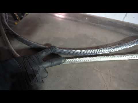
I can't even find where to buy it. called 2G HTS magnet-wire, here is a write up and some history of evolution.
https://citeseerx.ist.psu.edu/viewdo...=rep1&type=pdf
https://www.energy.gov/sites/prod/fi...tions_AMSC.pdf
2014Nano Shield introduced by Rea, which shows exceptional resistance to voltage stresses generated by high frequency, rapid rise time, and voltage spikes typically introduced by IGBT-type inverters, increased motor life significantly over standard MW-35C magnet wire under these voltage stresses and across a wide temperature.
Magnet wire can be found in electric motors, which translate electrical energy into mechanical motion through the interaction of magnetic fields and current-carrying conductors. These electric motors contain copper coils, which produce the magnetic fields.
Northrop Grumman Corporation has developed for the U.S. Navy the world’s first 36.5 megawatt (49,000 horsepower) high temperature superconductor (HTS) ship propulsion motor, double the Navy’s power rating test record.
Incorporating coils of HTS wire that are able to carry 150 times the power of similar-sized copper wire, the motor is less than half the size of conventional motors.
It will help make new ships more fuel-efficient and free up space for additional war fighting capability.
This system was designed and built under a contract from the Office of Naval Research to demonstrate the efficacy of HTS motors as the primary propulsion technology for future
Navy all-electric ships and submarines. Naval Sea Systems Command (NAVSEA) funded and led the successful testing of the motor.Last edited by BroMikey; 02-19-2022, 09:26 AM.Leave a comment:
-
Those are very interesting numbers from a coil that size, no matter WHAT material it is made out of. Do you have any idea the size of the rotor, the number of magnets on it or the size wire on the coils and LENGTH of wire or number of strands. I'm going to have to start experimenting with that closed flux loop if you can get THOSE kind of numbers from a coil of that size, because we already know that closed flux loop can be Lenz free. We have seen THAT in the Lindemann attraction motor, so it is possible in a generator.
Wanted to post some info on Bob French's replication of my little single coil motor single coil generator setup. The 7th grade science experiment. Bob says that when he aligns the motor coil directly across the rotor from the generator coil, the opposition magnets, neither N facing NOR S facing have ANY positive effect on RPM. In fact they slow the RPM of the setup no matter how he tries to use them. and only the magnet on the back of the motor coil causes any increased RPM. Just information folks. I am changing my setup over to his alignment when I get the chance to see if I get the same results. It's all very interesting. I am going to try to put together the same rotor and coil setup he has EXACTLY since I have a rotor that matches his perfectly, made by the same individual, and we bought our magnets at the same time from the same place. I just have all that stuff in a box and haven't needed it since I already HAVE a rotor, but it would be nice to have exactly what he has and see if I can get the same results I have been getting with my configuration, and the results he has been getting with HIS configuration. Data is good.Leave a comment:
-
This is one way how coils can be made to output excellent power. Keep the coil close to the core meaning for a 3/4" - 7/8" core no more than a 1/2" thick winding. Easy to say and hard to do. 1" magnets back to back no spaces. This is a max rating and Thane runs these continuous 3+ amps = 3 X 80 = 240 watts @3800rpm = 1520HZ
 Last edited by BroMikey; 02-19-2022, 02:17 AM.
Leave a comment:
-
Most likely it is not. What he is using is so-called "parallel path" of magnetic flux. You can read more details here:Originally posted by padova View Post

https://qmpower.com/wp-content/uploa...PPMT-paper.pdf
Been around for many years now. Just a more efficient motor. Which is what tinman figured out in his experiments as well. But no overunity.Leave a comment:
-
Hay Bro,Originally posted by BroMikey View Post
Actually, this isn't false, I actually wanted to point out to cross section area, nothing more,
and Bi has explained that in this case it isn't that important. And I think he's right,
because it's small difference in voltage output.
regards
And about Brad(Tinman) and hes motor, I'm not sure that it's OverUnity device, in some cases its very difficult to decide, because it's small line in the beatween,
basically you can not beat Natural lows, in this case low of conservation of energy, you must put out some work to produce energy, it's natural low.Last edited by padova; 02-18-2022, 07:50 PM.Leave a comment:
-
If you are talking about my drawing, watch the first video. It shows two N facing magnets on stands, (stator) and a piece of steel is coming down from the rotor and going between them with air gaps on both sides. Tricky.
I put one magnet IN the rotor with a built in air gap of plastic and a piece of steel covering it that REPLACES the piece that has to “stick down” from the rotor. Then you just have to adjust the one remaining magnet on the stator to have the same air gap as the permanent air gap you created between the steel plate and magnet on the rotor with the piece of plastic.
Same machine doing the exact same thing in a slightly different way. But would my way work? I tried it, and it taught me a lot about what I am doing with MY machine. DIdn't do what I thought it would do though. I learned one important principle about what is necessary. There are opposition forces between the two N magnets. If one of them is on the rotor it has an effect on the rotor. The two MAY have to be independent of the rotor in his design just like he has them.Last edited by Turion; 02-17-2022, 09:01 PM.Leave a comment:
-
What is the purpose of putting a steel plate in front of the rotor magnet?Leave a comment:
-
Here is the Modification I made of the basic idea behind Tin Man's device. The magnet is inset into the rotor deep enough to leave space for an air gap material (In my case I used some clear plastic I had on hand. Then a metal plate that could be screwed in place on both sides with inset screws that would mold to the actual curve of the rotor. Then the stationary magnet on the stator, or in my case, bolted to the bench as was the rotor, is adjustable so you can match the air gap on this side made of actual "air" to the air gap on the opposite side created by the piece of plastic. It is a simplified redesign of what Tin Man shows in the first video.Leave a comment:



Leave a comment: