Hi level,
Thanks for taking the time to check this out. I was pretty sure of what I was seeing but things like this can almost always have a way of fooling you into seeing something you want to see instead of what is really there. As we both know there are some on this forum that don't want reality to get in the way of their beliefs. I and you and several others just want to get to the truth. So thanks again for checking my set-up. I did find that I got the best ratio of current when I lowered the resistance to only 3 ohms. I have not found a lower resistor of high enough wattage to go any lower. But if I do away with the resistor completely then my ratio goes the wrong way. Still haven't figured out why that is but if we can substitute a load for the resistance that would be a good thing. My charge battery is still showing signs of being reconditioned so still waiting before I can do some more in depth testing of the overall efficiency.
I just lost the bidding on a couple of the Cen-Tech battery analyzers. So I may just have to use the buy-it-now and pay the higher price. I can see how one of those would be a valuable tool when working with this set-up. We can then see what we are doing to the batteries on a day by day and test by test basis. I will get one ordered before the day is over.
Later,
Carroll
-
Battery pulse charger - input/output current comparison
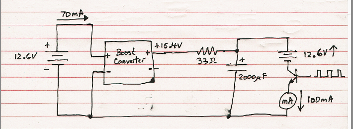
Hello citfta. I did a quick test setup of your battery pulse charger arrangement with a bit different values for the series resistor and charge capacitor, and I saw the same sort of results as you. I tried various settings, but to give an example, with the boost converter output set to 15.4V and varying the setting for the charge pulse duty cycle (I didn't measure it too closely as I was more interested in the current ratios for this quick test), as one example I was measuring 70mA into the boost converter at about 12.6V, and 100mA out of the boost converter at about 15.4V. I can't explain why that might be as I mentioned earlier, but I do know that John Bedini has described this exact same sort of current increase effect in regards to similar sorts of battery pulse charger setups he has done.
That was just some quick testing as I don't have much time to spend on it right now, but I just wanted to give you some feedback on your setup and let you know I see the same sort of effect. I was using a cheapo little analog multimeter to measure the output current in this quick test, but when I get more time I will try to do some better tests using my scope.
What I noticed in these quick tests is that the output current would be less than the input current to the boost converter at low charge pulse duty cycles, but as I increased the charge pulse duty cycle the input current to the boost converter would reach a point where it stopped increasing, but the output current would continue to increase until I could set it a fair bit higher than the input current.
Quick drawing of my test setup:
 Last edited by level; 07-12-2015, 07:11 PM.
Leave a comment:
-
Alternating Charge Batteries
Third test is a little disappointing. I think maybe something wasn’t connected well…?
Starting with:
B1 at 12.56V, 10.56 mOhms, 247 CCA
B2 at 12.56V, 10.79 mOhms, 245 CCA
Ended and after an 8 hour rest:
B1 at 12.56V, 10.72 mOhms, 247 CCA
B2 at 12.45V, 11.01 mOhms, 240 CCA
I’m running another test now…I’ll let ya know.
Matt, wow, good stuff. I almost got it on first read. I'm going to internalize it now. Thanks.
Carroll, the analyzer I got is a "CEN-TECH 12V Digital Battery Analyzer". I got it off Ebay for about $60 + shipping. The box says it is distributed by Harbor Freight Tools (Item 66892)
BobLeave a comment:
-
Hi Bob,
Those are interesting results on your testing. Even if this is only indirectly related to the Basic Free Energy Machine we are learning the best way to recondition batteries almost for free. Now if we replace your 15 ohm resistors with some kind of load maybe we can have a solid state Free Energy Machine. I still don't understand how these little boost modules allow us to boost voltage and not lose current but they seem to do just that.
I just checked my charge battery after a 10 hour rest and the voltage is now at 12.18. When I first hooked it up 3 days ago the voltage was 11.95 and it had not been used or charged for several months. So I am convinced I am getting it into better shape.
When I get it fully reconditioned I want to try your circuit with a load on each side and also a cap on the output of the boost module and dumping the cap like I am doing now. The boost module may be all we need to get a Tesla Switch type circuit to work properly.
I was also wondering what battery analyzer you and Dave were using. I only have a simple 100 amp load tester. It will give me some idea of the battery condition but not the kind of info you are getting. Looking on Ebay I see all kinds of analyzers but I would rather get what you and Dave already have so I would be working from same information you guys have.
I should add that the timing I came up with was because Matt suggested I look at the discharge into the battery and adjust to get the best charge into the battery. So Matt should really get the credit for the timing. I just followed his instructions.
Later,
CarrollLeave a comment:
-
Good tests Bob. I think your setup should not drain the batteries much since you are just mainly exchanging charge back and forth, and based on how John Bedini says the tesla switch works, the batteries should actually steadily self charge themselves. I think John Bedini said that one of the main principles behind the tesla switch is that when we pulse a battery with a pulse that is higher than the terminal voltage of the battery it causes a 'surface charge' on the battery to increase above the rest charge of the battery. If we then draw from this raised surface charge before it starts to fall back to normal too much to charge another battery or set of batteries, and keep this switching back and forth while making use of the higher surface charge on both batteries, the batteries are able to charge each other to a higher charge level. The problem is you have to watch that you don't over charge the batteries and damage them. The other consideration is does this method of getting the batteries to self charge actually cause the battery life to shorten quite a bit due to using up the battery resources much faster than normal? I guess we would have to do long term tests on batteries to see if their useful life is shortened noticeably by using the tesla switch self charging method or similar. I plan to get back to similar testing by the Fall. Very busy these days...Originally posted by [email protected] View Post
Last edited by level; 07-12-2015, 03:31 AM.Leave a comment:
-
Alternating Charge Batteries
Hey guys,
Got some good news. I have the results of the second run and they are as good as the first.
Starting with:
B1 at 12.56V, 10.91 mOhms, 242 CCA,
B2 at 12.56V, 11.06 mOhms, 239 CCA,
Ending with 9 hours of rest:
B1 at 12.56V, 10.56 mOhms, 247 CCA
B2 at 12.56V, 10.79 mOhms, 245 CCA
This comes from running the Alternating Boost Charge system with Carroll’s tuning of 15ms on the discharge and 60ms in the between. It was an one hour test and rested for 9 hours. The voltage stays up, the impedance is dropping, and capacity is growing. I like this. I’m running a third test now.
If the voltage stays the same and the capacity expands, doesn’t that equal more energy? level, if you take some mud out of the bucket, the water level (voltage) goes down (gives a lower reading) and the bucket can now hold more.
level, I am not running the Boost Modules at full power. I set them at 14.5V output so that the input would be lower and still be 2V over the charge battery. I hadn't thought about this until just now, but maybe that's why the voltage is staying at 12.56V instead of going up higher each time. (?) Also, I should note that I put a 15 Ohm resistor on the input of each Boost Module.
BobLeave a comment:
-
Hi Bob, that looks like a good simple way to do something very similar to the tesla switch approach, but you don't show any load in the charge lines to limit current and drop the voltage. You probably already know this well, but high voltage pulses at higher level current could potentially cause a lead acid battery to explode, so be careful. You may find that lower voltage pulses such as 15 or 16 volts or thereabouts may work just as well with less risk. Not sure what are considered 'safe' peak voltages on pulses to use with lead acid batteries... Anyone know? Yes, as was already discussed, just measuring the open circuit rest voltage on batteries doesn't tell you much about their actual charge level. The open circuit terminal voltage can be quite misleading.Originally posted by [email protected] View Post
Last edited by level; 07-12-2015, 03:25 AM.Leave a comment:
-
Hi Bob,
I agree with your idea that as you decrease the sulfation you increase the capacity. I was trying to think of a good way to describe this when I saw your post about the same thing. The best way I can describe that is to think of a 5 gallon bucket that is almost full of mud. The mud representing the sulfation or lack of capacity. Now if we leave the mud alone we can fill the bucket to the top with water but we really don't have much water do we? The water representing the charge we want in our battery. Now if we remove some of the mud we can replace it with water. So we need more water to fill the bucket but we are filling it with that we want instead of what we don't want. So the more mud (sulfation) we remove the more current we are going to have to put into the battery to recharge it back to what we want it to be.
I have a friend who has a VW Beetle that he had converted to electric. Several years ago he asked me about a way to recondition his batteries because they were sulfating in the winter when he didn't drive the beetle. At that time the only circuit I knew about was the Bedini SSG. So he built a couple of big ones and started using them. He called me and was disappointed because the battery voltages were going down and not up. I explained to him the SSG was not good at charging those large batteries but is was probably getting rid of the sulfation allowing them to take more charge. I told him to be patient for a few days and see what happened. Once he understood that he was satisfied and called a week later to tell me his batteries were in fact starting to take more charge and checking better under load.
All that brings me to my situation with what I am doing here. It appears the battery I am attempting to charge must have been badly sulfated also. I have been pulsing it for a few days now and it still has not reached a full charge. However I see two signs that it is being desulfated. The first sign is that the voltage will climb for a while and then either hold steady or drop off some and then climb again. The other sign is that each time I let it rest for a few hours the resting voltage is higher than before.
Several times when trying to recover a battery I have found when they want to keep taking a charge it may be because they have a shorted cell. There are two ways to determine if that is happening. If you check it after trying to charge it for a few hours you will find a hot spot on the battery or maybe even the whole battery will be very warm. The other indication is that after a rest time of a couple of hours or more the resting voltage will always be about 2 volts lower than it should be because of the shorted cell.
From some reading on the electric car forums and from information Matt has shared with me I believe this pulsing system is almost as good as you can get for restoring sulfated batteries.
Until I feel I have my charge battery fully reconditioned my testing is probably not valid for either proving this is charging more than it is using or for proving it is not. So I will continue with my reconditioning and then do more tests after that.
Later,
CarrollLeave a comment:
-
Alternating Boost Charging
Here's a better pic.
BTW, I may not comment on everyone's posts, but I read them all and appreciate your work. By and by we will come up with something.
BobLeave a comment:
-
Alternating Boost Charging
Hi guys,
Starting with this post I am using the circuit shown below. The batteries are LA and are labeled B1 and B2 and are never swapped. The charge is being sent back and forth.
I'm trying to do this on my phone...we'll see if it works. Here's a circuit that alternates the charging from one side to the other, back and forth. There doesn't seem to be any conflicting paths.
Also I bought a battery analyzer like Dave's (about $70). I think we need to track CCA as well as voltage. I haven't been able to verify it, but it seems to me that if we effect a battery so as to desulfate or increase its capacity, then the energy in the battery will "spread out" and show a lower voltage. Perhaps someone can chime in on that point.
I ran an hour long test last night with the circuit and measured it this morning...broke even, exactly even. I ran another this afternoon and will measure results when I return home in a few more hours. I am using Carroll's 15ms dump and 60ms cap filling, by going high for 15ms then low for 22ms on each side.
I forgot to note that the Arduino is running off its own separate third battery.
BobLeave a comment:
-
Hello citfta. I recall that John Bedini has talked about exactly this sort of effect that you are seeing. John also pointed out that the lower you can keep the input current to the switching circuit, the higher the COP will be, which seems to possibly be what you are describing here.Originally posted by citfta View Post
After thinking about it more, I think basically if you take the output voltage of your boost converter times the output current from the boost converter, that is basically your output power from the boost converter. You would really need to have the RMS current measurement, but the average current should be close enough to understand what is happening. Batteries are not like normal resistive loads of course, so that is why it is hard to get a handle on this for me from the output power perspective. I am still not certain about this, but anyway John Bedini seems to have taken what I said above as the actual output power for this type of battery charging circuit. John Bedini has been there and done all this sort of thing years ago, but we are all just catching up now even with lots of help from John Bedini over the years. Because this setup is dealing with sending a charge current to a battery, which is not a 'normal' type of load, it is hard to say if this really could be COP > 1 even if you confirm that output charge current is higher than the input current to the boost converter. Batteries are electro-chemical devices and analyzing what is going on with them, especially when using pulsing, is a whole different kettle of fish to normal resistive loads, as I am sure you know well. It is all still really interesting however.
If you want to get rid of the series output resistor, one way you may be able to do this is to use an oscillator with complementary outputs, such that when one output is high, the other output is low, and vice versa. Replace the series output resistor with another transistor, and switch the two transistors with the complementary outputs such that when the capacitor charging transistor is on, the battery charging transistor is off, and vice versa. This way you have isolated the battery charging cycle completely from the input, so when pulsing the battery you are not drawing any output current from the boost converter. I don't know if this will be better than using a resistor, but it might work. You will still get some power consumption in the transistor switch that replaces the series resistor, but if you use a good low On Resistance switching transistor you can keep that to a minimum. You will probably have to play around with your duty cycle percentage as you have already been doing to look for a setting with the best performance. Just an idea.
Last edited by level; 07-11-2015, 11:41 PM.Leave a comment:
-
A final report before I go to bed. I have found I could reduce the resistance to about 3 ohms and get the best run to charge ratio I have been able to get. I have 3 10 ohm resistors in parallel which gives me a resistance of about 3 ohms. By again reducing the boost circuit output I now have almost a 3 to 1 ratio of charge current to run current. I again tried to eliminate the resistor completely but cannot get that to work as well as it does with a resistor. I only get this ratio of 3 to 1 if I keep the input current to about .25 to .75 amps. If I raise the output adjustment so that my input goes up to an amp then my ratio begins to fall off. In other words if my input is about .5 amps then my output is just shy of 1.5 amps. But if I raise the input to 1.5 amps the output only goes to 3 amps. So my most efficient ratio is when I keep the input down around .5 amps. I hope all of this makes sense. It has been a long day and I am ready to head for bed.
Later,
CarrollLeave a comment:
-
Hi Matt,
Yes I seem to get the most efficient charging with these batteries if I charge the cap to about 14.75 volts and dump it more slowly than I was. I am also charging with a longer dump time. I am now using a 15 millisecond dump and 60 millisecond recharge time. Over all current seems to be the same but the battery is taking it better.
I think what I am mostly doing right now is just reconditioning the charge battery. Once I get that done then I can see if this circuit will be able to charge batteries and sustain itself too.
I was able to get the resistance down to 10 ohms by turning the boost circuit down quite a bit. But that also seems to have improved my run to charge current ratio. I am still not able to find a combination that will let me do away with the resistor totally. I did try adding more resistance but that did not improve things any.
I am trying to take it slow and easy on reconditioning this battery. I am almost out of batteries to play with. Time to take the shorted ones back to the salvage yard and trade them for some more to play with. I really think this circuit might be the best one I have found for reconditioning the batteries even if it does not prove to be self sustaining.
Thanks for the tips.
Later,
CarrollLeave a comment:
-
Hi guys,
I am old enough to remember the days when all car radios had vibrator circuits. You could always hear the hum of the vibrator. There should be a thread in the Eric Dollard section of this forum about the device Eric had. There was a discussion about it on here about a year ago or more I think with pictures and the schematic of the device.
CarrollLeave a comment:
-
I think this thing has a mechanical vibrator that changes 6V / 12V into operating voltage for the tubes. I remember seeing (and hearing) one operate as a youngster:Originally posted by ZeroMassInertia View Post
Vintage C 1954 Civil Defense Motorola 2 Way Radio Model T43G 1 for Parts Repair | eBay

Leave a comment:
Leave a comment: