
You have to flip two of your arrows.
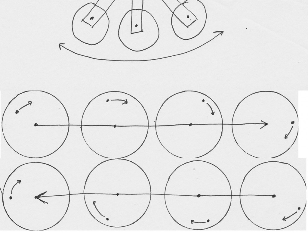
Front and back, left and right, take one of the green arrows and flip it toward yourself , when the front rotation is moving in toward the structure , the back should be moving out of the frame.
artv
-
Magna, I'm not handy with computers, here is the video address, https://youtu.be/gk0zCpLlwm4
I put it on you tube, but I don't know how to do linking stuff.
But it is much clearer.
artvLeave a comment:
-
I for one would be grateful to see any footage shylo has of the device. Is there a way you can get it to YouTube or something, shylo?
Aaron,
The problem I see here is that if there is, at the top, one cross-bar from back to front then there should be a second cross-bar from left to right also. And these hypothetical cross bars would be moving in a scissor like fashion, because, when the upper shaft out front is leaning to the right and the upper shaft in back is leaning to the left, then it can be seen that the upper shaft on the left is leaning toward the back and the upper shaft on the right is leaning toward the front. And I don't perceive any evidence of a second cross-bar going between the left and right side. Even in the better quality video.
Your illustration bellow appears to indicate the 2 cross-bars move in the same direction and is inconsistent with the movement stated above and seen in the video.
What are your thoughts on this?
MagnaMoRo
Originally posted by Aaron View PostLeave a comment:
-
crossbar end mechanism
This video is direct from British Pathe who owns the copyright to this video clip. It is the best copy available online that I know of. It is better than the version I saw several years ago that got me started on this project.Originally posted by shylo View Post
The upper mechanism that I show in the small vid clip is not clear because I zoomed in so much. The video clip shows the crossbar moving - it is even apparent in the zoomed in version - the movement is evidenced by the pixelated crossbar movement. It is only apparently stationary for a couple frames while the end swing arm piece moves with the shaft.
I think you are the first to state that the crossbar doesn't move.
Anyway, this pic by Michael John Nunnerley earlier in this thread is what I'm trying to say. Early on, I was leaning towards it being a little wheel or bar on the end but it is more like what is in this drawing:
Michael is calling it a "cam" - that is the same as the swing arm or end bar that I'm referring to. Michael posted that last June: http://www.energeticforum.com/258438-post271.html
That is Skinner's method for imparting an elliptical orbit to the input lever/shaft.
Leave a comment:
-
Go see Aaron youtube channel
Hello all
Aaron did many experiments on that device evidence by is many films on Youtube.Go have a look it might help explain what he is saying.
This: https://www.youtube.com/watch?v=NW93RhylMRE and many more
Peace and LightLeave a comment:
-
Hi Aaron, Can I ask ,What you are basing your opinion on of the crossbar moving back and forth? Is it from viewing the film only or do you have some other source?
I have a video that is clearer than yours (I tried to attach it ,but it's an invalid file type).
I think the rotating of the little plate at the end of the crossbar is giving the illusion of the crossbar moving back and forth. In the video I have I can see the crossbar is stationary.
I agree with your explanation of the translation plate, That is where the gains will take place.
Not trying to misinform anyone ,just like to know what your info is based on.
Thanks artvLeave a comment:
-
1939 William Skinner Gravity Power
Fair enough - but seeing my observation dismissed as nothing more than being a pulley, belt, etc... gave me the impetus to offer an explanation of my stance, which heavily opposed your counter stance.
I'm not against your opinion, but I will elaborate on what I am claiming what I am claiming and why.
That last video I did is not very clear. I zoomed in too much but nevertheless, you can see the pixelation is identical in 2 frames of the crossbar indicating no movement, while the input lever actually advances it position ahead of the crossbar. You are free to redo exactly what I did with higher quality and you will find that the upper part of the input shaft is not fixed to the oscillating crossbar. That in itself is "smoking gun" evidence right from the source that they move independently of each other as I showed in a video with the smaller bar or swing arm at the end of the cross bar. Since that is the case, it shows that the total movement is indeed an elliptical orbit that is imparted to the upper part of the input lever.
Before going into the upper weight analysis, do understand that the end of the crossbar travels in a crescent-shaped path? If we take the hour or minute hand of a clock and have it rotate around a fixed central axis and that hand moves between 1130pm and 1230pm (back and forth), that is a crescent shape and not a strict linear path. It is an oscillation that is surely back and forth but not a direct line. However, for the sake of examples, a straight linear path can impart the same rotational movement to the translation coupler. Is there an advantage to the crescent path? There may or may not be but both are irrelevant to the fact that with a linear or crescent path coupled with the belief that the input lever is fixed to the oscillating crossbar, both cause rotation of the translational coupler.
Even without the extra elliptical input from the crossbar>swingbar>level mechanism, analyzing the movement of the translation coupler as I did with graph paper in one of my vids, the lower shaft is still moved in an elliptical orbit. The center of axis of the top part of the upper shaft is moving - the frame of reference from which it rotates around is moving. The movement the translation coupler is rotational while it is ALSO moving back and forth imparts an elliptical orbit. This is accentuated by the upper part of the input lever also being moved in an elliptical fashion.
Anyway, do you or do you not understand that the oscillating crossbar end does indeed travel in a crescent-shaped path?
I mostly received a history lesson on their father's work and what it was about. This was over multiple conversations. Who as involved, how Skinner got ripped off by greedy lawyers and business partners, the opposition to his work that he encountered and a few principles that are gems that I've been trying to impart to anyone that is interested in this discussion - and who was working with Skinner the most during these projects. There is more that is private but is not essential to the understanding of the machine.
Originally posted by MagnaMoRo View PostLeave a comment:
-
Originally posted by Aaron View PostOriginally posted by Aaron View PostNo Points are being argued AT ALL by me over the workings of the machine.Originally posted by Aaron View Post
To me, all of this is about open source information.
I made the .gif to help clarify to myself what is happening with the machine.
I believe the .gif offers the best visual to the date of creation.
It is my duty to share my results as a free gift to the open source community. I did so on your forum because of your personal interest in this machine.
Each interested party must make up their own mind as to what they see in it.
The way that I made the .gif was also listed here as open source information, so others might know how to do it themselves. Not necessarily as some sort of defense of its authenticity.
I see a circular orbit. There may still be more to know. but even in your video (not as clear as the .gif) I still see a circular orbit.
I also should see the 1st level masses rise and fall in the video and or the .gif if there is actually an elliptical orbit of the upper shafts (like in the linear video). I just don't see that either. Do you?
What information (documents, pics, schematics, etc.) did the family offer you?
MagnaMoRoLeave a comment:
-
Yes I agree AaronOriginally posted by Aaron View Post
I don't see a circular orbit, I see the orbit of the planets
which seems to be found in nature most of the time. Even
atoms and their electron orbits do not follow a circular
path.
It is clear to me that it is a wobbling. Now that I have looked
at the video more I am beginning to see more going on than
I did the first time.
Also the animation of 20 frames did not clear everything up, it
was watching Skinner show his lower large weight swinging
on a single lever or shaft it rotates on.
I will be looking at that for a long long time before I can say
anything one way or another, but it does follow an elliptical.
And yes the friction losses are not even an issue to speak of
with a 1200 percent COP. Beyond my simple statements I know
little else.
What has me spellbound is the action above with the cables
pulling weights up and down one opposed to the other and the
surprise that this huge wobbling mass does not break off.
It is so well balanced with one wobbling axes countering the other
that I stand amazed in sheer awe. Those steel pucks and arms
are very heavy.
I will look forward to any further work in video form that you might
deem important down the road.
Take no prisoners. The misinformation mind set seems to saturate
our entire world of thinkers who have taken the bait and still think
they are right.
MikeyLeave a comment:
-
elliptical orbit
I'm reposting this, looks like the first time I posted it, the video didn't actually embed properly.
[VIDEO]https://www.youtube.com/watch?v=lA9wHJsFzm4[/VIDEO]
Originally posted by Aaron View PostLeave a comment:
-
elliptical orbit
I honestly can't see to much authenticity in the arguments against what the video is clearly showing right there.Originally posted by BroMikey View Post
And this line of logic...
@MagnaMoRo - no problem with you posting your opinion of what the machine does, but I'll make the facts very clear so people are not mislead by ill-informed opinions.Originally posted by MagnaMoRo View Post
@BroMikey - Well, if there is doubt that Skinner would go through all that effort for a linear drive - to do what? Just to have the lower weight's shaft simply go in a circle?
Then attach that shaft to one side of a pulley and spin the pulley or gear with a direct drive from a motor or with a pulley and ditch all all the input lever mechanism all together!
If the goal is to make that lower shaft simply go in a circle, to "go through all the effort" - makes no rational sense to argue why he would go through all the effort then to make it a circular orbit.
And...
The argument against extra friction - it is inconsistent with the belief that all the dog and pony show is there just to make a circular orbit.Originally posted by MagnaMoRo View Post Talk about "Extra friction!"
There are double standards in the logic.
Again, to believe all the extra upper machine contraption is there to create a circular orbit for the lower shaft - which adds way more friction than is necessary to create a circular orbit but an insignificant extra amount of friction to create an elliptical orbit - well, maybe I'm the only one that sees the inauthenticity with that...
And even arguing extra friction is irrational for a machine that is supposed to be 1200%.
These legitimate "overunity" machines are not perpetual motion machines where a mass is in movement and has to overcome friction - that is not even an issue or the point of an over 1.0 COP machine. It's a non-sequitur sort of - has nothing to do with anything. Friction in these machines are a minor loss and are not the thing to be overcome in order to have their gains. The goal is not to overcome a minor loss that is in all legit over 1.0 COP machines, but to leverage nature in the most efficient way possible so that the machine can regauge itself to the highest potential difference on each cycle. The friction is nothing more than the cost of business.
Once single principle can be applied to that might increase the friction less than 1% in order to take it to multiple COP? Yeah - give me that extra friction!
Perhaps I'm the only one that notices that there is more opposition and discouragement to the fact that the machine runs in an elliptical orbit than anything else in this thread - is QUITE INTERESTING!
Leave a comment:
-
why elliptical is needed
The John device is simply a very symmetrical equilibrium mechanism that rotates the lower weight's shaft in a perfect circle - and in the videos, the more weights distributed out from the shaft to spread it around it's circumference moves it even more towards equilibrium, which moves in the direction of what a flywheel is supposed to do. It accomplishes what some people in this thread think the Skinner machine is doing, but they're very different.Originally posted by drak View Post
When it is locked in a circular orbit, there is no gravitational advantage because the lower weight is at a fixed height and it defeats the whole purpose of trying to convert gravitational potential to real mechanical work. In a circular orbit, since there is no change in height of the lower weight, there is no dipole or potential difference change in relationship to the lower weight's position at any point of the orbit. That prevents gravitational potential from entering the system to push on the weight from a higher level to a lower level - thereby doing real work that is additive to our own input. That can only happen with an elliptical orbit.
I explained it many times here, but anyone can try it out.
Take a pencil and put the point on your desk on a paper or something. Make sure the tip stays at the same place. How grab the eraser and move it around in a perfect circle - or close enough to observe the obvious, which is the fact that the eraser does not change height.
Now, rotate the eraser in an elliptical orbit - make it a long narrow ellipse to exaggerate the effect to make it easier to see. The more narrow and elongated the ellipse, the more acute the angle between the paper and pencil becomes and at the far ends of the ellipse, the eraser is at the lowest height. Bring the eraser to the narrow part of the ellipse by the "center" and the eraser is at the highest point and the angle between the paper and eraser is the most obtuse.
In the Skinner machine, when the lower weight's shaft (top of shaft) is at the center (between the far elongated points of the ellipse), it is at the highest point and therefore, the lower weight is the highest and most top heavy. There is more gravitational potential available to it at that position than at any other position. Not only is the entire mechanism snapping that shaft towards the far point of the ellipse, but that is where the most gravitational potential is assisting this lower weight as it falls towards the far end of the ellipse.
We have additive forces here that is more than our own input. We have the upper weight's momentum, which is a reactive force to the input lever that doesn't counter the input motion, but assists it in its elliptical orbit. We have long leverage from the long input lever's length - another mechanical advantage. The momentum of the upper weight does most of the work and the input lever's energy requirements are only to make up for the loss. Then we have some momentum from the lower weight and then the gravitational input that pushes on it to the far edges of the ellipse - plus the acceleration of the lower weight around the edges of the ellipse.
With all of that, there is way more than enough to push that lower weight from its low point at the edge of the ellipse up to center point where it is at the highest with a lot of energy to spare.
Whenever the lower shaft moves, the upper weight will ALWAYS FALL to the inside of the incline. And every time the machine regauges itself (lower weight moving from low point to high point by moving from ellipse end to the center) that re-establishes the dipole to increase the amount of gravitational potential energy (M*G*H) available to do more work.
All of that is completely taken away by rotating the lower shaft in a circular orbit where it is at a fixed height. Gravity cannot do anything since there is no change in height, there is no regauging at any point in the process, etc... in a circular orbit, it is a completely closed system - closed off to gravitational potential energy, which defeats the entire aim of turning gravity into work.
Anyone can
Leave a comment:




Leave a comment: