
wow! That's a very impressive build!
I noticed that starting at about the 53 second mark of the video the
upper weight farthest from the camera doesn't turn at a constant speed.
It seems to speed up and slow down.
I'm not sure about the others.
the two to the right of the camera seem to turn at the same speed.
What horsepower is the motor?
I hope you can do what Peter suggested.
good Luck.
Tom
-
Brilliant!!
Armandino,Originally posted by armandino View Post
Totally excellent model! WOW, that was a lot of work. This should allow you to determine, once and for all, whether a circular motion is capable of producing a gravitational gain in a mechanism like this, or if the elliptical motion and pumping action Aaron is talking about is required.
Now comes the hard part: TESTING! First step is DON'T BREAK YOUR MODEL!! You do not have to make it go 100 rpm to test it. Right now, your model is going almost as fast as Skinner's was in his film. That should be fast enough for initial testing.
You will need a watt-meter on your drive motor and a calibrated braking mechanism (dynamometer) on your mechanical output. The first data point will be to see the RATIO of input to output. If loading the output has a 1-to-1 ratio of loading the input, then Aaron is right, and it is not really producing a gain. If the input to output ratio is different than 1-to-1, then a circular drive may still have merit.
I will say that early on in the understanding of this machine, Aaron and I did try a number of circular drive mechanisms, (at my suggestion) and none of them showed anything other than a direct linkage between input and output. I was quite disappointed, but it did reinforce Aaron's evaluation of the motion taken by the upper drive system.
I look forward to your test results.
PeterLeave a comment:
-
needs elliptical input
Nice build but you will never find what you are looking for with circular input of the upper input levers. But since you have it circular, you might as well take the measurements and compare to elliptical when you want to do what Skinner actually did.Originally posted by armandino View PostLeave a comment:
-
pumping action
hello, it was very tiring but I finally put together four modules that, in this video https://www.youtube.com/watch?v=f_MUqwa-pZc
rotating with 45 rpm. The mechanism has a moment of acceleration-pumping. The lower weight has a greater pumping of the upper weight and I realized this effect dislocating the lower vertical axis. I moved the base anchored to the floor of 5 cm. consequently the rotation is no longer in a horizontal plane but inclined therefore the weights have a moment of ascent and a descent where is the gain, and I have synchronized the fall of all the weights opposed in pairs so as to cancel the vibrations. the result is a moment of acceleration of 600 kg weights. I will bring to 100 rpm. I hope that everything remains intact. Then I execute the first load test with a generator derived from a wind turbine fall and destroyed. What do you think?
armandinoLeave a comment:
-
pumping action
For the upper input lever to rotate in an ellipse, it doesn't require anything that you mention. The upper input lever is connected to a small swing arm at the end of the oscillating cross bars. This causes the lower weight to change it's center of balance and causes the pumping action 2 times per rotation.Originally posted by Danny B View PostLeave a comment:
-
IF the pivot for the upper shaft were not directly above the pivot for the lower shaft, the weight would create a pumping action.
The shaft would move in a circular path BUT, the weight would have a "period" of climbing and a period of falling.
There is another possibility for a pumping action. I used a constant-velocity universal joint,,, Rezeppa.
IF you built with a normal 4-point universal joint, they are NOT constant velocity. The lower shaft would speed up and slow down depending on the phase of the u-jolint. Once again, I don't know how much effect this would have if all 4 weights are locked together.Leave a comment:
-
examination of eccentric mechanisms
Skinner's machine has 4 driven shafts. This complicates any attempt to drive them in an elliptic path. Here is a vid of a device that generates an elliptic path; https://www.youtube.com/watch?v=5ukHWJA_pOg
Here is an alternative to the Scotch Yoke; https://www.youtube.com/watch?v=zae2ZePQTwQ
Another; https://www.youtube.com/watch?v=xPg_nubcYOg
One more; https://www.youtube.com/watch?v=xPg_nubcYOg
All of these devices use some kind of sliding guide. Skinner moves his weights in pairs so, it would take 4 pairs of sliding guides.
Here is a double Scotch Yoke but, because it has a center axle, it describes a circle. https://www.youtube.com/watch?v=iedyiuLBRbE
If a device doesn't have a center axle, it is very difficult to drive.Leave a comment:
-
Progress
After MUCH thought, I'm not convinced that the upper shaft runs in anything but a circle. If you watch the vid (for the umpteenth time), you see that the maximum angle of inclination for the north-south shafts appears to be equal to the east-west shafts. What portion of the rotation is truncated? The drive can't very well be a reciprocating slider. If the drive were a slider, it would have to have a link to convert linear motion into rotary motion. This could never describe anything but a circle because the anchor of the link would act as an axis for a circle.
Anything with an axle must describe a circle when in motion,,, at a given, fixed distance from the center. The "swash plate" idea doesn't look viable because the drive motors would have to be inclined. It would also need Heim joints for drive connections. You would expect the resultant elliptical orbits to be apparent by comparing the north side to the west side.
The only way that I can see to drive the top shaft in a ellipse is to drive it in a track that would have to be below the link. I see no sign of a track.
The top of the shaft is easy to see and there doesn't look to be a bunch of complicated linkage.
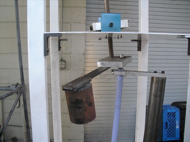
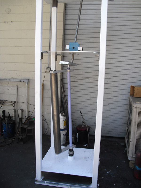
The top of the lower shaft has about 40 lbs of constant sideways pull. It demands to move outward as far as possible. It is only restrained by the wobble plate. The wobble plate is restrained by the limit of angular deflection of the upper shaft. Whatever orbit the top of the upper shaft follows, the top of the lower shaft follows. They are solidly linked in their relative angles.
The sideways pull of the top of the upper shaft is about 10 lbs. But, it has about a 5--1 leverage against the sideways deflection of the lower shaft.
The upper shaft prevails on position.
I bought a motor and speed controller. 12 VDC. I also got a Manta motor-generator. I'll just keep everything 12 VDC to start.
The wobble plate is locked into position by the gimbal. If the upper shaft is driven by a link of some sort, I don't see any way for the upper shaft to follow any path except circular.
Skinner repeatedly mentioned "eccentrics". I believe that the quad shafts are driven by an arrangement much like a windshield wiper. This would qualify as eccentric. For 4 shafts, this would need 2 linkage rods and 2 cross rods.Leave a comment:
-
Upper weight
I used about 55 lbs of lead for the upper weight. It's in a steel sleeve.
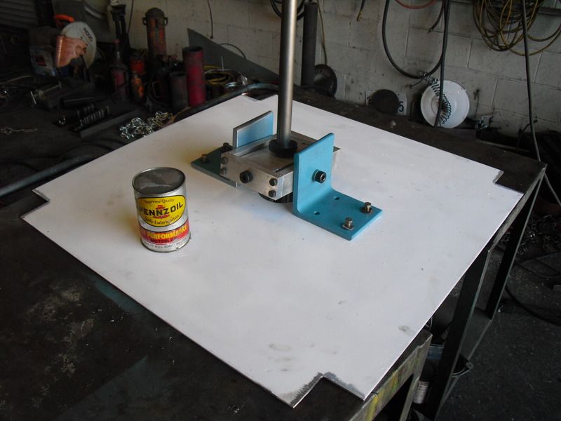
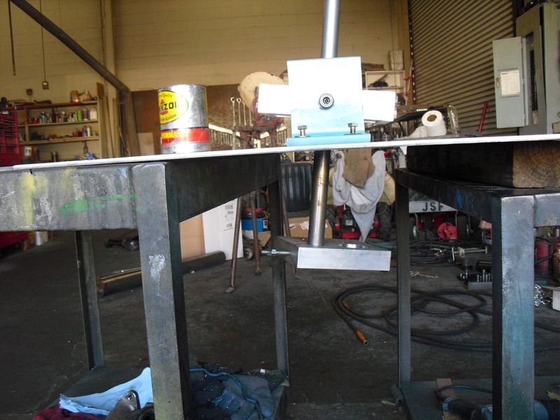
Next comes the top plate and shaft drive. The upper shaft currently runs in an artificial orbit defined by the hole in the plywood. It's too big at the moment. There is a huge amount of push against the periphery of the wood circle. Any elliptical path would have to overcome the natural fall of the weighted shaft.
I thought that I had the answer in the design of the gimbal. Wrong!
2 thoughts come to mind;
The gimbal could be designed so that it had a built-in limit to travel in one axis.
The upper pivot point for the drive could be offset from the center of the gimbal. This machine is VERY sensitive to level. That would make the weight tend to fall to the lowest position. That still wouldn't make the shaft break away from it's outermost possible orbit.
I'm going to set up a drive and see what happens.
In the original Skinner video, 2 pairs of weights are oriented in the X axis and 2 are oriented in the Y axis. The opposing in-out movements are what keeps the machine from shaking apart. North-South move as a pair. East-West move as a pair and are clocked to North-South.
The first 6 seconds of the vid are NOT oriented in either axis. If they were, you could look at the 2 pairs of shafts to see just how much eccentricity is built in.
BTW, the film is misleading. It never shows him starting out the several hundred pounds of weight with the little string.Leave a comment:
-
Weight relationships
I'm still trying to work out the size of the upper weight. In this picture, you can see the lower shaft restrained in an artificial orbit (the hole in the plywood). It takes X amount of force in pounds to pull the shaft away from the described circle.
CIMG0125_zpskjnqxl14.jpg Photo by DannnyB | Photobucket
In the video, Skinner moves the lower weight with his hand. The upper weight appears to be freely rotating in it's preferred path and bringing the lower shaft/weight along for the ride.
That would mean that the top weight has a weight of X+ to overcome the natural fall to the natural path of the lower weight. The relationship is complicated by the fact that the upper weight is positioned 90 degrees offset from the natural inclination of the lower weight. If it were in apposition, it would only need to weigh X+. Since it is offset, I believe that it needs to be X++.
I need to do more building and more testing. It appears that the lower weight is always 90 degrees from achieving it's at-rest position.
To be continuedLeave a comment:
-
Base bearing
I realized in this way the sealing system and of all the load rotation. it is de bearing of the hub of the wheel of a machine (used by many brands). this hub is ideal for our realization as within two different diameter bearings are installed. in this way it acts as a conical bearing which can weigh many Kg. and resists lateral traction as if it were mounted on the machine. in the upper part I installed a crown of the transmission of a Quad, step 420, and with chain connect all four rotors.Originally posted by armandino View PostLeave a comment:
-
gimbal and more
Originally posted by Danny B View Post
hello, let me introduce my realization of the gimbal installed in my system. I used a constant velocity joint of a small Italian car (Panda). I cut it in two for the length by removing the post of a thousand lines. in this way the remaining piece allows it to be pierced by the axis tilted. I added the rubber dust cover and you're done.
I hope you put to good use.Leave a comment:
-
pics
Leave a comment:
-
will work for dimensions
I figure 10 inches from the gimbal to the wobble plate. Does anyone have different ideas? I have the material for the gimbal. Just need to do the machining.Leave a comment:
Leave a comment: