
yet another walter skinner replication
dooo dooo dooooo dooo, dooo dooo dooooo doo
*insert ufo imogee
Hello ESM'rs,
im currently reading through this thread,
love gravity machines and pendulums,
always have,
I AM Determined too work a replica of some youtube videos i am inspired by,
and i plan too post the images and experiences on the forum, - hoping peeps are going too help me out,. - im currently lathe'ing some mdf drive pulleys, and will post the progessess tomorrow,, - the machine is days away from completion and testing.
PEACE>YO
-
Originally posted by velacreations View Post
I know this is an old 'thread' but IF you are still reading here, I have EXACTLY what you are asking for!
However, due to regular and systematic SABOTAGE on this Forum, I will only reveal this info to you personally (or perhaps others who are GENUINELY interested) since I am NOT interested in ANY form of argument!!
You can contact me at lbanki at bigpond dot com (FIX the email address)
Cheers,
Les BankiLeave a comment:
-
When I run into data limit problems I make trip to the local library where they have free wifi and using the download plugin that Aaron mentioned in my firefox and download the video there then I can watch it as many times as I want ast home. If you have any broadband free internet access that is what I would recommend you do also.Last edited by zipster1967; 02-06-2017, 01:19 AM.Leave a comment:
-
Stop the squeak
Danny I can really appreciate your work.
The squeak is not indicative of such good work. the amp draw tells me something is not true. It "the squeak" happens always at the same point. The top shaft is pointing left, in the picture, the transmission coupler is pointing to the back right-hand quadrant, and the Lower shaft is pointing to the right.
the shaft without the motor gearing connected would tend to make me think the mechanism would come to rest with the levers in approximately this position.
I would love to take it home to do more developments with but I am fresh out of space. big offer for the right person.Leave a comment:
-
Scale up the gravity motor
Bump !
I understand what Skinner was trying to do. He appears to have had limited finance. The weights are hollow. All the weights are "clocked" so that they don't collide. If there were a "pumping action", it would have to be done with 2 weights moving in at the same time that 2 weights were moving out.
Locking the 4 shafts together would have to be done with either gears or chains. They didn't have cog belts at the time. Locking the lower shafts together means that any pumping would have to be done to all 4 at once. Otherwise, the effect would be cancelled.
If there were a pumping action, it should be apparent by watching the flat-belt. I don't see it. Also, any oscillation of speed would cause problems with using the lathe. I don't see any need for pumping action. Nor do I see any evidence of it.
The machine is straightforward. Leverage is the critical factor. All the output depends on the angle and length of the lower arm and the amount of weight on it.
Skinner spent 14 years working out his ideas. There might very well be a way to improve it but, it works like it is. Best to copy his design theory though, not his build. I understand how to build the "quad" machine. There is nothing tricky or critical about it. The machine is easy to scale-up. Just keep the angles the same.
Skinner used a PTO to drive his stuff. It shouldn't be too difficult to put a big diameter rotor like a wind-gen under the base and drive it directly. A homopolar motor could be used also. Lots of possibilities.
If anybody wants to take my machine and use it for development, you're welcome to take it. Since it isn't a balanced quad, it must be attached to a building.
Leave a comment:
-
Skinner machine design concept
I have been studying the Skinner gravity machine for a few months and been doing some testing and I believe I have come up with a design that would work but I just have to collect the materials to build it in a small scale to test the concept. If anyone could take a look at my design and let me know if they think it would work and if not then what is wrong with my assumptions.
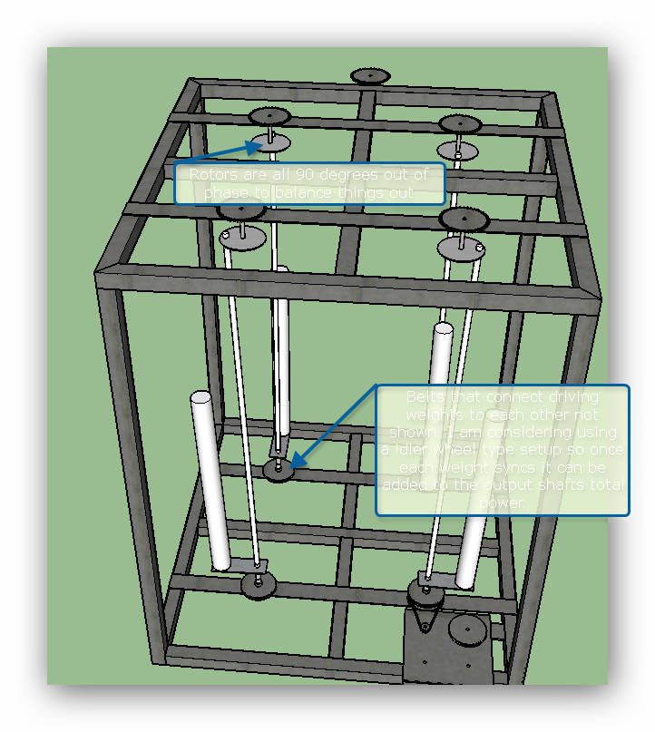
Leave a comment:
-
Leave a comment:
-
Armandino, That is a very impressive build. It was very astute to offset the weights so that would act as one mass. There is one problem though. According to your doc that you posted, you have paired the weights adjacent Not opposite. Skinner has paired, synchronized weights that are diagonally opposed. This aligns the considerable mass transfer over the center of the machine.Leave a comment:
-
Hello, I wish in these drawings illustrate the processed for the timing of the lower weights. Also the upper levers have the same timing, but remember that the independent rotation from that of the lower weights.Leave a comment:
-
Offset pivot
That's quite an expensive machine that you have built. AND, quite dangerous. I certainly wouldn't go to 100 rpm.,,, especially with just one connection and a chain on the lower weight.
Earlier, I wrote; "The upper pivot point for the drive could be offset from the center of the gimbal." Apparently, you have offset the lower pivot point rather than the upper. (5 cm.)
Was there any reason that you moved the pivot of the lower weight rather than the upper weight?
I'm doing load testing now. It takes about 30 watts, DC to rotate 150 kg. at 60 rpm.
The reason that I ask about you moving the lower pivot as opposed to the upper pivot is; all 4 lower weights MUST be locked together to do actual drive work. All 4 weights MUST be synchronized to keep the machine from shaking apart. If you lock them together, how is any one weight going to free-fall on the downhill stroke?
On my build, The arm that drives the upper shaft only positions the shaft. It does not drive it in rotation. The upper shaft is free to rotate or not. After my initial load testing, I'll move the upper pivot off-center. I expect the rotation of the shaft to "retard" on the uphill and "advance" on the downhill.
It remains to be see just how much of this variable speed can be imposed on the lower weights if the 4 shafts are locked together.Leave a comment:
-
Looks like the weights are not in step properly with their
dance partner diagonally across.
If you watch the original Gravity Power video at the 13 second mark
you can see as they slow down that when any weight is turned
toward it's opposite they are both as close together as possible.
This applies to both top & bottom weights I think and shown more
clearly in the film with the bottom weights. This is necessary to
keep the whole machine from gyrating apart or across the floor.
I advise against increasing rpm unless you reset the chain to
coordinate them.
that nut on the bottom of the motor shaft is loose.
keep going!
TomLeave a comment:
-
hello, thanks for the encouragement. E 'fair to say that I share the thought of Aaron on the effectiveness of the elliptical motion. What I have realized is a movement that is characterized by a tangential acceleration allows to increase the kinetic forces that arise from the movement itself. are laws of physics to be applied as the bible. I have tried to apply an acceleration at the entrance of the higher weights and I noticed negative behavior because this machine uses a transmission output from the effect of a drag lever of the lower weights with slingshots effect. to get it is required that the upper movement of the lever enters into "coupling phase" with lower weights. in fact, the weight of the push needed otherwise only turn the upper lever otherwise weights would remain firm. The acceleration is busting this coupling. of course it was my test with the mechanics available. it may be that other mechanisms you can achieve different effects. however, I have reported the primary drive with a linear rotational input. because I am absolutely convinced that an acceleration system allows ottenerre a gain, I moved the application on lower weights decentralizing vertical axis of 5 cm. and synchronizing the other rotors while achieving a fall of weights in a single moment. I got an acceleration of the rotation that, given the total weight of 600 kg, achieved significant energy gain accumulated what must yet be quantified, that's why telle my concerns about the structural seal. the synchronism of torque rotors allows me to undo uscillanti forces that would otherwise be uncontrollable. we hope well.Leave a comment:

Leave a comment: