Announcement

Collapse
No announcement yet.

Cap Dump Circuit

Collapse
X
 
  • Filter
  • Time
  • Show
Clear All
new posts

  • Dave45
    replied
    Pos and Neg boost converters

    Originally posted by BroMikey View Post
    Twin boost converters with bases firing from diodes.

    Double duty twin booster converter? I think

    Mike
    Yep, looks like the coils are wound bifilar.
    If you think about it pos in one winding neg in the other the bifilar coil is a capacitor of sorts.

    Leave a comment:


  • Dupe
    replied
    Twin Boost

    Hi mike, yes a nice little circuit to play with...basically a bistable oscillator principle. frequency dependent on the inductance in the main. Be careful within the RF regions though!!! as this could possibly pump out some interference.
    Regards Dupe.

    Leave a comment:


  • BroMikey
    replied
    Plus and Minus Boost Converters


    Twin boost converters with bases firing from diodes.

    Double duty twin booster converter? I think

    Mike

    Leave a comment:


  • Dave45
    replied
    Beautiful Circuit

    Nice
    Персональный сайт - JOULE THIEF

    Leave a comment:


  • BroMikey
    replied
    Dot Dot Dash

    Originally posted by Dave45 View Post
    No offense Mike

    I dont expect anyone to build my idea's ...................

    We have to be honest with ourselves, if you developed a circuit that put out more than it took to run it would you post it? probably not, not because of greed but because it would be very dangerous.

    Study every circuit you can find but follow your own path, just building everyone's nonworking circuits will get us nowhere.
    Hi Dave that is a milestone essay

    I am glad to hear from you on this level of communication because a lot of experimenters feel the same way.

    In other words hat I am seeing is a sort of dot dot dash type of exchange on the web where they don't mind shooting of a few emails without pictures of their projects or putting out some photo's without explanation. As long it is an incomplete entry they feel safer.

    I see that and I wonder why but I think you have summed it up.

    If I get an overunity circuit going I will post it and we can go from there.

    Thanks for being honest.

    Mike
    Last edited by BroMikey; 09-10-2014, 06:06 PM.

    Leave a comment:


  • Dave45
    replied
    No offense Mike
    The circuits have not been tested, still in the planning stage.
    Not sure what you mean by software, I draw them up in ms paint and study them, I will build and test when I have the gates figured out.

    I knew we had to collect neg as well as pos and am developing a circuit to do just that, but yes its still in the planning stage.

    It has to be rational and simple, action reaction.

    It also has to ring true if you know what i mean, sometimes you just know.

    I dont expect anyone to build my idea's I just put them out there for consideration, I will build them in time.

    We have to be honest with ourselves, if you developed a circuit that put out more than it took to run it would you post it? probably not, not because of greed but because it would be very dangerous.

    Study every circuit you can find but follow your own path, just building everyone's nonworking circuits will get us nowhere.

    Leave a comment:


  • BroMikey
    replied
    Yeah me too

    Work work work just got in.

    Sounds good for the definition Dave great diagram. Does this mean that sound of these circuits you post are actually put on a bread board?

    Or are the dozens of circuits you post still in the planning stages of theoretically analysis?

    I don't mean to sound critical here Dave but I have asked about which circuits have ever been tested and which ones are guess work. I understand that any circuit can be generated from software but finding one that doesn't burn out parts and works takes real hands on.

    I think many people see your circuit generator as a sort of gaming generator where it becomes addictive to see what the software can kick out next time.

    Is that how it is? I hope you do not find these questions offensive.

    In other words, people who might otherwise actually build one you your many circuits can't because they don't know which one is a real circuit and which of them are hypothetical.

    See what I mean?

    I love circuit generating, because without that art we would be stuck drawing out everything on paper to scan it in like the old days.

    Mike

    Leave a comment:


  • Dave45
    replied
    The circuit when finished will output DC
    Still studying and working out the gate drives
    The spark gaps will stop the coil from drawing from the power supply and ionize the dielectric ambient, it also allows only one polarity to hit the coil.

    I started a big project at work so havent had much time here lately but still working it out.

    Leave a comment:


  • BroMikey
    replied
    4 boost circuits

    Great diagrams.

    This one is a quad-Boost could run it up to 100-200v at say 5 amps I think but to get the extra into that open coil I thing running at 1 amp may be best.

    Or is that a buck/boost? I see PNP and NPN.

    What would be the best device to use in the load?

    Should it be a high voltage load? Like an electric motor?

    Wait I do see very small spark gaps. What would they do if I used a motor in the load? What would the spark gaps do? Or what effect does a spark gap have other than to throw off sparks?

    Don't spark gaps oscillate? Are those gaps oscillators?

    Mike
    Last edited by BroMikey; 09-08-2014, 10:47 PM.

    Leave a comment:


  • Dave45
    replied
    DC spark gap

    Leave a comment:


  • Dave45
    replied
    Static Electricity explain control eliminate remove Electrostatics Inc
    If the material being neutralized is charged positive, it will immediately absorb negative ions from the static neutralizer and repel the positive ions. When the material becomes neutralized, there is no longer electrostatic attraction and the material will cease to absorb ions. Conversely, if the material being neutralized is charged negative, it will absorb the positive ions being generated by the neutralizer and repel the negative ions. Again, once neutralization is accomplished, the material will no longer attract ions. See figure below.

    Leave a comment:


  • Dave45
    replied
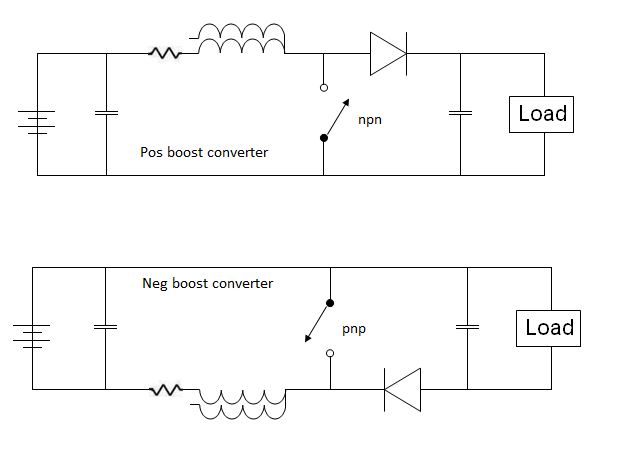
    Mark on the other forum made an observation both circuits are boost converters, and after consideration I concluded he was right one is a neg boost converter and one is a pos boost converter.

    Im like you resistors waste energy but in this instance are necessary.
    When pos and neg meet energy is released mostly as heat, if the two meet at the coil heat is produced in the coil and the coil reacts in both directions.
    But if a resistor is placed on one side and the resistor has more resistance than the coil the two will meet at the resistor, only one polarity is hitting the coil, only one reaction from the coil.

    Let look at the pos boost converter
    The cap next to the bat is loaded up 12v neg on one side and 12v pos on the other when the switch closes the polarity's see a route to each other and move through the circuit to join.
    If there is no resistor the polarity's both hit the coil but if there is resistance on one side that polarity is slowed and only one polarity hits the coil.

    Electricity is the separation of charges pos and neg, they seek neutrality and to be neutral they must join. opposites attract

    Leave a comment:


  • BroMikey
    replied
    New understanding

    Originally posted by Dave45 View Post
    But I did learn on my journey, both sides of the coil get hit when the transistor turns on, but found a way to suppress that.
    As usual a picture is worth a thousand words.
    Hi Dave

    It seems like what you must be saying is that normally speaking each of us opening and closing the switch have not been making a very good unidirectional impulse on account of simple circuit actions.

    Improving the one direction switching is the next step.

    Tesla said to make an impulse in one direction, not both, all at the same time.

    So what it looks like you are learning is a way to stop the batteries from being hit on both sides at once so as to gain a more pure one direction pulse.

    With all of the resistors put in the line to do that will waste power but maybe it will still be worth it?

    This is all I can get out of your last post since I already know you are following experiments to produce results that most circuits are unable to make.

    So did you see a good effect from it?

    Mike

    Leave a comment:


  • Dave45
    replied
    Originally posted by Dave45 View Post
    Yea got carried away, back to basics
    But I did learn on my journey, both sides of the coil get hit when the transistor turns on, but found a way to suppress that.
    As usual a picture is worth a thousand words.

    Leave a comment:


  • BroMikey
    replied
    Originally posted by Dave45 View Post
    Yea got carried away, back to basics
    Hey Dave

    At the end of those last coils you could put plates and call it an air ozonation air purifier.

    Great way to remind me of pos/neg IONS.

    Mike

    Leave a comment:

Working...
X