
Power In Power Out
Hi UFO,
Sure call it 100W input.
I was thinking a full wave bridge rectifier with cap(s). 500uf should even out the ripple probably at least 200V with those big spikes. 1000uf would be better.
No one can easily disagree with DC power measurements.
Increasing the value of your exciter cap would likely reduce the amplitude of the big spikes.
L192
-
I meant to comment on your "description" about that wave...it made me laugh...Originally posted by Listener192 View Post
Did you ever heard about the "h wave"?:
It would be good if you do some research about it...
John Bedini (RIP) produced it on his oscillators...and below are some other Thread on this Forum about it, as there is vast info on line about it:
The "h" wave form
Also on OU.com a Thread named:
KAPANADZE COUSIN-DALLY FREE ENERGY
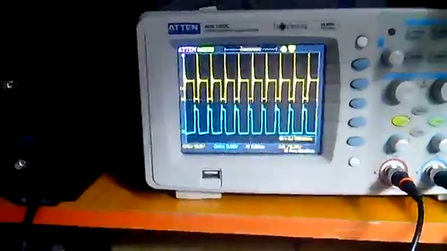
Only thing is...those previous waves were either Positive or Negative...very rare to see them MIRRORED on both sides of the zero line...but now we have it "alternated" and very symmetrical (even pos-neg values)...
Regards
UfopoliticsLast edited by Ufopolitics; 10-26-2017, 01:19 PM.Leave a comment:
-
Thanks L192.Originally posted by Listener192 View Post
Could round it up to 100W for easier comparatives, Input linear PSU would either go above the 50V to reach two amps on the Meter mark...or what I did, reach 50V exact and be under two amps line...anyways this are "nickel and dimes here, like I said, round it up.Originally posted by Listener192 View Post
That was a 12V/40W Halogen Bulb... however, if you connect it to a 12V Battery, reading 12V before loading it, then add same meters V&A with bulb, it will show around Ten (10) something volts OR a VOLTAGE DROP of about 2V and around 3 some amps...where voltage will keep decreasing -as Amperage- as ON time passes, since battery is NOT a constant generator of energy...in the Generator there are no decrease of energy while loaded, no matter how long it is connected.Originally posted by Listener192 View Post
What am trying to say above is that the Voltage read while loaded is a Voltage DROP Difference (not full output voltage) after load is consuming the power. (and -of course- this is completely dependent upon the Load Characteristics, in this case we have an "Amp Hog Bulb" which takes between 3 to 4 amps to lighten up)So IMO there should be a V Read BEFORE loading it to know Full V Generated Out.
Nope, I wrote before Inner Output 2 was NOT loaded, but just connected to Blue Scope Channel.Originally posted by Listener192 View Post
The "ideal" way each one of this Modules from this system works... is when we connect Inner-Outer Output Coils in series, which are being Induced by the same Alternating Magnetic Field...However, BOTH Coils must be "balanced", balancing meaning having exactly same number of turns, same gauge type, in order that Induction disbursement would be equal distributed between both...and we can go here as sophisticated as measuring each coil Impedance and Inductance to make sure we are as close as possible, since there is a slight difference in the thickness of each.Originally posted by Listener192 View Post
When you say, "can you rectify the output", are you referring to:Originally posted by Listener192 View Post
1- Before diodes with AC Caps?
or
2-After Diodes with DC Caps?
In either way...which capacitance do you suggest?...I believe should be Low Capacity, in order to have real time readings and not stored over time with higher capacities right?
Just wanted to say that the Inner Coil by itself, as is, could power up a 120V AC Drill...pretty heavy duty...without altering Input Amperage...Input Voltage will drop a bit, to then recuperate back to previous measure.
But the same exact deal applies if I set an Output Coil of the same spec's (as gauge, #Turns, etc) on the Outside of the Exciting Coil.
Understand that so far?...Which means that if I connect both output coils in series, I will have a slight amperage drop, while voltage would be about doubled.
And I have not mentioned we could also add two more Output Side Coils at each ends of core...which would have power as well...
Regards
UfopoliticsLast edited by Ufopolitics; 10-26-2017, 12:15 PM.Leave a comment:
-
Power In Power Out
Hi UFO,
Any protracted development effort like this, is interesting.
So your DC power supply is showing lets say 50V @ 1.9A = 99W
Your outer output coil although interesting, when shorted, was only showing
6.78V @ 2.78A =18.8W when loaded
I don't know if your inner output coil was loaded for this test also.
The inner coil is the more interesting one, as you said this was capable of supplying 80V @ 2A. Without a math function on a digital scope used with a current clamp, it would be difficult to be sure about the power of that square/spikey alternating waveform.
If you get the time, can you rectify this output, smooth it with a cap and load the output then see the maximum DC power you can pull versus the DC input?
Thanks
L192Leave a comment:
-
Shorting Outer Output Coil (Part 3)
Hello again Listener,
Now watch what happens when I short the halogen lamp fed by outer coil, (in order that Amp meter reads Max Surge Amps) ...still same meters reading VDC and Amps DC on left...
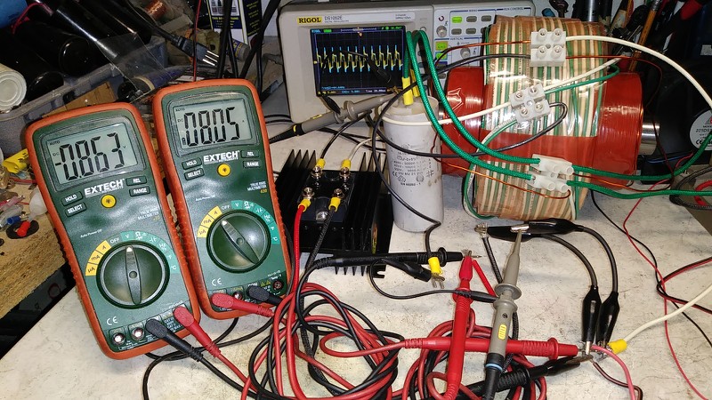
Exactly what I was writing before...First, volts NEVER drops to Zero...here is showing 863 millivolts (almost one (1) volt).
But look at DC Amps...Yes, that's right...exactly 8.05 Amps after passing diode bridge losses (of course AC Amps would be more than that)
Then look in the background to Scope...the signal (from Inner Output Coil) is still there, a bit shortened, but is there.
What do you think so far?...
Refards
UfopoliticsLast edited by Ufopolitics; 10-26-2017, 12:14 AM.Leave a comment:
-
Part 2 Answer to Listener...
Sorry but my PC (still with old mother boeard is slowing down by the minute...it cost me a lot of work just to download these images...Originally posted by Listener192 View Post
Ok, (about your last question) yes, we could measure AC Out with regular meters, before diode bridge...as, like I wrote before, I can power ANY AC Tool running excellent.
Now, pleaseallow me to finish showing rest of Images...
Input is shown below from my Linear PSU...
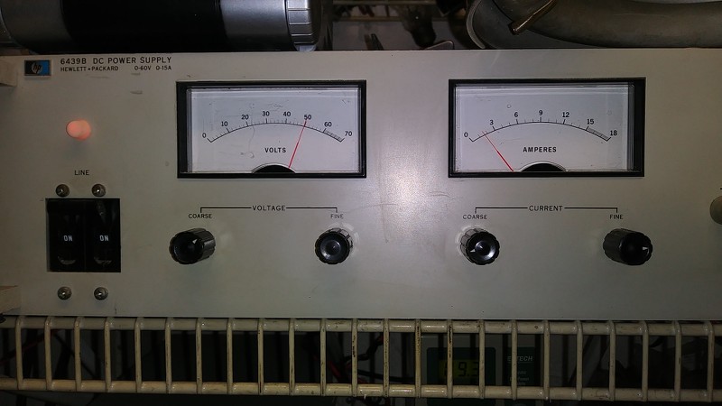
Is set to 50V and not reaching 2.0A (a bit less)
On the right hand is the low voltage side with four ultra caps and driver...:
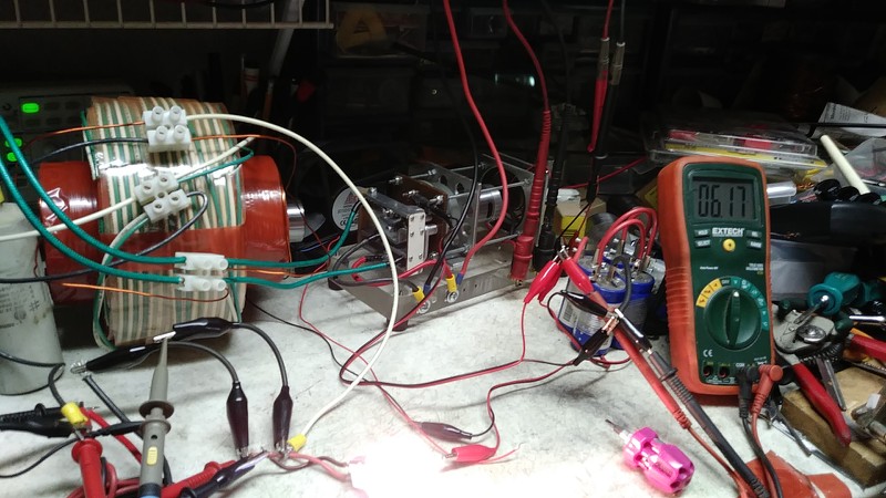
On next image (Next Post) I will show what happens when I short Bulb...
UfopoliticsLeave a comment:
-
Hello ListenerOriginally posted by Listener192 View Post
Yes, however, remember the rotary switch driver converts it to what I call an "Alternate DC" or "ADC"...Originally posted by Listener192 View Post
Kind off but not exactly a smooth sinewave...NOT just like AC from the wall outlet...actually it is an exact "copy" of my reversed ADC Signal to Exciter...take a look:Originally posted by Listener192 View Post
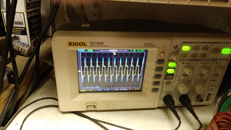
Yellow Chanel is Input
Blue Chanel is Output from Inner Coil.
Now the whole set up is shown below, I have TWO Output coils, one on the INNER side closer to center core, which is 14 gauge and like seven layers all wound along cylinder core, same length as exciter.
The Second Output Coil is the Outer one (green-white) made out of house wire awg 12, (We could afford to use this wire since it does NOT get hot at all) but, very bulky due to insulation and it does NOT extends all along cylinder as you could see:
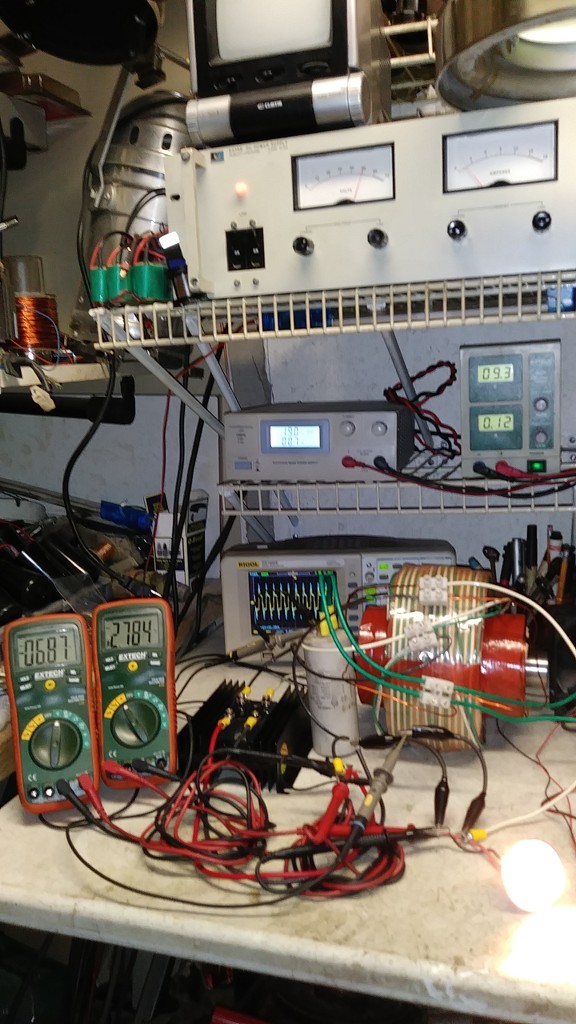
This Outer Coil is feeding the 12V Halogen 40W Incandescent Lamp with DC, after passing the Diode Rectifying Bridge (Black Box with Heat sink at Left), and meters on Left are showing V (6.87VDC) after fully lighting the bulb, which is consuming 2.78 Amps DC.
The Inner Output Coil is just connected to Blue Chanel Probe and no load added...it outputs around 80V and like 2.0 amps.
RegardsOriginally posted by Listener192 View Post
UfopoliticsLast edited by Ufopolitics; 10-25-2017, 09:15 PM.Leave a comment:
-
Power In Power Out
Hi UFO,
Your input is DC so that makes power in easy to calculate.
Is the output a sinewave , i.e. can you just use AC meters to measure V & A?
Regards
L192Leave a comment:
-
Hello Listener,Originally posted by Listener192 View Post
Btw, I wanted to thank you for your suggestion previously about connecting the AC Cap at all times with Exciter Coil(s)...It really enhances Induction!!
The Power Input I try to keep it steady around same numbers, which is around 50-60 Volts and from 1.0 to 2.0 Amps, that's from 50W to 120W.
Now related to Output I have tested MANY different output coils configurations...some give me MUCH higher Amperage, like from 7 to 10 Amps, but lower Voltages like 25 to 36 Volts, while others, the ones I have run AC Tools with, it gives me 115-120 V and like 1.5 to 2.0 Amps.
I am still not happy with the Exciter coil configuration, so I am going to change its geometry a bit without changing wire length or gauge, in order to keep using same Input. As I am VERY SURE, I could extract MUCH MORE Energy when Exciting configuration have the right Dynamic-Response to Higher switching ratios.
The System reuses the spikes from exciter at swapping-reversing times two times per cycle, which I store in a typical DC Cap Bank (10 Caps 100V/1000UF) to avoid arcing in those stages and power up the cooling fans to keep energy flowing...this extra energy is not counted to measure OU, as well as the switch motor takes around 18-20V and like 700 milliamps, not counted either as losses.
I could try to Loop System with switch motor, but then I will need a controller to adjust speed and right now I don't want to complicate things till I am happy with main system.
I have a small bank of Four (4) Ultra Caps (12V/1 Farad) and recovered-processed spikes does charge them as system runs, completely independent from main Input-Output while running fans (2), now, if I increase this Ultra Cap bank, I easily could also run the switch motor, which is what am looking forward to do in a future.
Regards
UfopoliticsLast edited by Ufopolitics; 10-25-2017, 02:14 PM.Leave a comment:
-
Power in Power Out
Hi UFO,
What is your measured power in to power out ratio, with the setup you have reported OU on?
Regards
L192Leave a comment:
-
Evolution of a Process...
Hello Zardox, Hello to All,Originally posted by Zardox View Post
Nope, there is absolutely NOTHING to be moved related to Cores or Coils.
what we are moving here is the virtual Magnetic Field while cores are completely static...actually that was the main idea on Original Patent.
If you try to pull core while system is operating, besides the suction force you will feel, you will note an alteration on the output which directly relates to a voltage decrease, while input amperage will drop as well.
it will DECREASE Induction, HOWEVER, if we REVERSE Coils Input Voltage it will show it DOES INDUCE BOTH WAYS...so I developed this new signal where I am REVERSING ALTERNATIVELY the Input Voltage Polarities to Exciter coils...and yes, it does work as it Increases Output considerably.Originally posted by Zardox View Post
You actually could wind it any way you prefer as a test mode, a simple, back and forth wind ascending in layers will do perfectly well for BOTH, Primaries and Secondaries.
When I used the single brush driver, square wave, just one side, I wound it bifilar and I was creating an Image (Mirror) meaning OPPOSITE SPINS of the field with an LC Tank on the second wire...it works as well...but OU was not that much of a difference above Input, here I tested several different options in windings without much difference which will create doubts and a war of measurements...so I disregarded this method and kept on developing.
Now, it is a very LOUD and CLEAR difference, as there is a huge gain on Amperage and Voltage versus Input Power (V+A)
In my conclusion after all this development is that by pulsing with a single brush, always positive, I have realized we are only "pumping" energy out in a Half Cycle, which can not develop to greater outputs over input. Or in much simpler words...Figuera's "pumps" fields ONLY N-N, while it should be half cycle N-N and other S-S, so you get a closer idea.
At this time I only have ONE Exciter Coil which Pumps N-S in a half cycle, then S-N in the following cycle. Now when I have said TWO exciters, at cycle 1 Exciter 1 would be N-S & Exciter 2 would be S-N, now set them facing each others with "y" in between and we have:
Cycle1= N-S(Y)S-N
Then
Cycle2= S-N(Y)N-S
EDIT1: Now, I have NOT tested the option above as I am reaching great results with just one exciter which does N-S then S-N as it is enough to Induce two secondaries over and inside...SO, IMHO I am not sure which way would be better for the "y" secondary Output in between...if as shown above OR as a continuous Magnetic CHAIN like N-S(Y)N-S on Cycle 1 then S-N(Y)S-N...BUT, this would just take a swap of Terminals connections of just one of the exciter coil to driver rotary switch, then compare outputs difference.
Besides I have TWO more secondaries wound above and inside Each Exciter Coil (not shown above). So in the above arrangement I will have a total of FIVE (5) Secondaries with only TWO Exciters.
Hope this helped you somehow, sorry for long post, but this is for others as well, building the Figuera Generator...
Regards
UfopoliticsLast edited by Ufopolitics; 10-24-2017, 04:55 PM.Leave a comment:
-
couple of questions for my dense brain
I have been doing some magnetic tests on a small primary coil wound the way you showed.
It reminds me of a dual wound solenoid and makes me wonder if there would be any advantage in having the core being able to slide back and forth?
Also I am unclear about the best way of winding the output coil as your video shows what looks to be a single coil. Your drawings show a series of coils. But I wonder if it should be wound like the primary coil.
Obviously we have moved beyond the original patents.Leave a comment:
-
Besides OU...
Hello,
Besides reaching OU...with our systems we will have other "anomalies" (that I actually see them as "goodies") which comes with the "territory" of NOT FORCING MECHANICALLY an EMF Induction...
First, and I consider it as essential....is the fact that when we SHORT OUT our Output Coils to measure FULL AMPERAGE...Voltage DO NOT drop to Zero, but remains at Positive Values.
Second, when connecting whether a DC or AC Motor (whether at DC Diode filtered Output or Pure AC Out terminals) And mechanically loading it...Input Currents drops are minimal, as also this drops only last seconds till they return to previous operating levels, I believe these are Lenz manifestations which can't keep long due to a NON PHYSICAL Field super fast moving rates through Mass...
At either of above situations, output coils NEVER rise not even one degree of temperature, while exciters keep operating at normal temperatures (warm).
If we do ANY of the above tests on ANY Rotary Generator, Voltage will drop to Zero...PLUS, if we keep shorting for too long...we will burn crispy (well done) our generator coils...and possibly our Amperage Meters will fry as well...while the ICE farting machine will start coughing to get to a final stall...
What really gets hot is our Iron Cores, which I believe is due to the very fast rate of changes in their ferromagnetic polarities orientations at molecular-atomic levels...or maybe the so called Eddy Currents....or Joules heating...which I would be testing laminated cores to see if this higher temp decrease...if not, then Heat Sink end Plates of Aluminum would do the job...and maybe a couple of cooling fans....
Who cares?...after all we have a lot of extra energy to spend right?...
Regards
UfopoliticsLast edited by Ufopolitics; 10-23-2017, 12:16 PM.Leave a comment:
-
Hello ElCheapo,Originally posted by Elcheapo View Post
Yes, that's right, and as a matter of fact, I am getting full induction at around 2600 RPM's...that's somewhere around 40 Hz, it is easy to note that if you increase speed, we start decreasing induced power.
Not necessarily it is "a good sign" that Input Currents go down when output is loaded...the ideal device would be the one where currents drops are minimal while output delivers HIGHER Amperage than Input.Originally posted by Elcheapo View Post
See, the "INCREASE OF THE RATIO OF CHANGE" from the exciter Magnetic Field, should be the ONLY reason that increases Output Currents (and Voltage as well)...while Input Currents remains stable.
Correct.Originally posted by Elcheapo View Post
Definitively by increasing number of turns will increase output...HOWEVER, depending on the wire gauge (awg) you are working on at Output Coil "y", by increasing #turns your output currents would decrease and voltage would increase...Originally posted by Elcheapo View Post
I highly disagree that it is "Transformer Effect", and am sure you know transformer basics...where the MAIN FLUX TRANSFER travels through a CLOSED CORE, while the FLUX LOSSES are located at the surrounding SPATIAL AREA around Coils.Originally posted by Elcheapo View Post
In our case, we have a straight cylinder (or square cross section) LINEAR CORE, with Infinite Air Gap...and so, if we reconsider our geometry, we are using basically those supposed to be SPATIAL LOSSES to generate an EMF induction.
Remember Cook's Patent?...it is exactly an open straight core with secondary wrapped above exciters...
The "Side to Side" Induction with an air gap between is a plain and simple result or consequence from the mechanical rotating -Two Parts- generators structure. And it is MUCH weaker than capturing the Rate of Change right from the aligned, CENTER of any electromagnet generating a Magnetic Field...they just can not afford to also rotate the generating field-coils...and having no static parts, because simply, it won't work...besides the similarities to the Homopolar Generator or the "N-Machine" from DePalma...
Regards
UfopoliticsLast edited by Ufopolitics; 10-23-2017, 05:22 PM.Leave a comment:
-
Hi UFO,
"That's right. C.F. might have been using only 25hz. But just keep in mind.....You don't need that much high freq, basically very low numbers should work, not even above 60 hertz."
The higher the frequency the higher is efficiency.
"Isn't that good? Current goes down while output to load goes up.What I believe is going on in your case, is that Induction is taking away currents from your exciters"
In both cases resonance is responsible. parallel resonance means high impedance so current WILL go down.
If you are striving for a self-sustaining system then you certainly want to have as low a power input as possible.
Now that I know that it works the small "y" coil will have many more turns added and my straight cores replaced with 2 fully wound "C" sections facing
each other for much better "B" field and with 2 "y" coils.
I have umpteen things I'd like to try but it all takes time.
""Take your your y coil off then get the two exciters coils and cores and approach them without touching iron to iron, could use a small rubber damper as gap and Idk if you have bolts on them, which would be ideal to prevent high vibrations, this gap is approx around 5 mm.
Then wrap your y coil ABOVE and around BOTH Exciters LENGTH, trying to reach both ends...normal winding, back and forth layers.
I'm sure I'd get a much higher output by doing this.
But in my opinion that is just a transformer.
That "y" coil has to be completely divorced from the exciting coils emf. It's only the changing MAGNETIC fields between the 2 poles that can communicate with the "y" coil.
So no, I have many other better things to try. Thanks anyway.
Regards
ElcheapoLeave a comment:

Leave a comment: