Announcement

Collapse
No announcement yet.

Re-Inventing The Wheel-Part1-Clemente_Figuera

Collapse
X
 
  • Filter
  • Time
  • Show
Clear All
new posts

  • Ufopolitics
    replied
    Originally posted by seaad View Post

    ....
    At 2) and 3) a rapid current variation can be working at the same time as "the consecutively" or "the more and more" electromagnets is to be conneted step by step in a slower rate. And here the discussion of " make before brake " maybe comes in. It can maybe be important that the next coil is connected previous the disconnection of the first in a situation of Vandering Magnetic Fields?

    ....

    Regards / Arne
    Definitively, the way that Figuera does that "make before break" is by having Brush contact TWO ELEMENTS in Commutator...

    This allows the "simulation" of MOVING FIELDS to be OVERLAPPED (Applied to the Rotary Pattern in the Patent you showed before, NOT in Figuera, since it is LINEAR)

    HOWEVER, when Two Coils are energized at the same time, even for a millisecond, the Current I, suffers a "fluctuation" AFFECTING the COMMON MOVING FIELD PROJECTION (generated by a SINGLE COIL)...which in my understanding is NOT GOOD for Induction purposes.

    It works though...but not the way we all wished to...


    Regards


    Ufopolitics
    Last edited by Ufopolitics; 03-03-2018, 03:46 PM.

    Leave a comment:


  • seaad
    replied
    I have toggled the film frame by frame and found that it is always between 6 -12 relay LEDs lit simultaneously. . . . . 10 12 10 10 6 8 10 10 8 6 10 .... 6 8 10 10 10 8 8 8 8 8 12 10 12 8 8

    It's not only a simple coil connection sequence!
    Read also at , Free Energy | searching for free energy and discussing free energy , about the doubts to the relay freq compared with showed output frequency 60.6 Hz !!

    Regards / Arne

    Leave a comment:


  • Ufopolitics
    replied
    Hello Arne, thanks for the videos and info!

    Well..."The Principle" behind those whole bunch of wires plus hardware, is very simply and GENERALLY DEFINED AS:

    "A MOVEMENT OF THE MASSLESS, TRANSPARENT (TO OUR EYES), WEIGHTLESS AND VIRTUAL MAGNETIC FIELD(S)"

    In the case you have shown, we just replace "MOVEMENT" by a "ROTATION" in above sentence, to make it "more specific" to this application.

    Something that I have been telling about, over and over and then more over and over in THIS WHOLE FORUM for a LONG TIME.

    If you want to understand what he is doing...it is simply demonstrated (even though pretty rough) by his piece of wood with two rotary magnets (First Video)...and so when he inserts it within the MOTOR STATOR CORE, then we see the two small magnets spinning...I did that, done that before.

    He is using Arduino Microprocessor plus a bunch of transistors, plus a bunch of relays, just to achieve the SEQUENTIAL EXCITATION OF EACH COIL IN THE MOTOR (STATOR) FRAME...


    And so, he is STORING all the Energy in the 18 SUPERCAPS, in order to allow the "JUMP" or use that circuit as a TRANSFER SWITCH, which allows the SELF OPERATION of the whole machine.

    To me, IMHO... just the fact that the System is able to SELF-SUSTAIN, is a GREAT ACHIEVEMENT, REGARDLESS OF OU OR NOT.

    What I liked about his setup, is the AC MOTOR STATOR which have -ALREADY BUILT IN- sequenced and OVERLAPPED COILS, and obviously He is exciting each one in a continuous, sequenced order with a DC FIELDSPACE-TIME FIELD"


    My two pennies worth...


    Regards


    Ufopolitics
    Last edited by Ufopolitics; 03-03-2018, 03:26 PM.

    Leave a comment:


  • seaad
    replied
    Here is another impressive system similar to Figuera. Working as I think according to my A)-thoughts in post #2691 above.

    170 watts in - 1600 watts out - looped - Very impressive build and video


    Regards / Arne

    Leave a comment:


  • seaad
    replied
    The show goes on

    Clemente Figuera

    Clemente Figuera

    Regards / Arne

    Leave a comment:


  • seaad
    replied
    Summary

    In my pursuit of the Figuera OU Effect I have found some parts in the patens texts more important/ interesting than others, according to me. (Right now ) . . . See A, B, C below.
    Much of the talk about resistance, commutators and such are lots lots of patent 'smoke'. And is more or less; education in how to make current variation. And even the wiring circuitsery / sketches. They are just sketches. In the patents you can read: " what is sought is the patent for the application of this principle " !


    A)
    (1908) " circulates a proper current, which is taken from one foreign
    origin into one or more electromagnets, magnetize one or more
    electromagnets"

    " and while the current is higher or lower the magnetization of
    the electromagnets ((one or more)) is decreasing or increasing and varying"

    B)
    (1914) " but in no case is there any communication between the induced coil
    and the inductor coil "

    C)
    (1914) " and we will collect from these induced ((y)) the resulting
    phenomena experienced from those inductors. ((N, S)) "


    A) One or more electromagnets
    Here is a situation of Rotating/ Vandering Magnetic Fields possible. Or just varying the amount of something.

    See even the patent dicussion some post above. The Rotating Magn. Fields OU genny.
    A stationary cylindrical electromagnetic core, made of one piece thin laminations stacked to desired height, having closed slots radially distributed, where two three-phase winding arrangements are placed together in the same slots, one to the center, one to the exterior, for the purpose of creating a rotational electromagnetic field by applying temporarily a three-phase current to one of said windings, and by this means, inducting a voltage on the second one, in such a way that the outgoing energy is a lot greater than the input. A return will feedback the system and the temporary source is then disconnected. The generator will run by itself indefinitely generating a great excess of energy permanently.


    1) Just connect a current/ voltage variation to all electromagnets simultaneously/ alternately, (parallel, series or groups).
    2) Or connecting to One electromagnet after a another, consecutively. Back and forth, back and forth.
    3) Connecting/ adding to more and more electromagnets in parallel or series. And disconnect/ subtract coils one by one backwards again.

    At 2) and 3) a rapid current variation can be working at the same time as "the consecutively" or "the more and more" electromagnets is to be conneted step by step in a slower rate. And here the discussion of " make before breake " maybe comes in. It can maybe be important that the next coil is connected previous the disconnection of the first in a situation of Vandering Magnetic Fields?

    B) No communication y ==> (N, S)
    I have conducted a test closely related to the "2SGen" 2SGen, an amazing tiny Solid State Generator by JL Naudin

    In my test I could not achieve NOT y ==> (N, S) (One direction Only) but instead NOT y <==> (N, S) (bi-directional non-connection)

    As J. Naudin I used a fully wound toroid as input coil (N, S) and a large width wounded coil(loop) as output coil (y) around the toroid as a equatorial belt around the toroid-"belly" .
    With a Sinus signal connected to the input toroid coil. No signal at all could be measured from the surrounding output coil!
    But when some neodymium magnets where placed on the side of the toroid core a strong signal comes from the loopcoil (output). The same in opposit direction if (y) was used as input!
    With the input coil in parallel resonance I achieved a 75% transfer Input to Output with this a simple experiment.


    C) Phenomena from inductor coils (N, S)
    Here the author just say that some phenomena (OU??) originates/ arises from from the primary side. And the secondary coils/reels (y) just collects the energy.
    How and What is the questions?


    Regards / Arne
    Last edited by seaad; 01-29-2018, 10:13 AM.

    Leave a comment:


  • seaad
    replied
    UFO
    Some Ohms left somewhere hiding inside yor magpies nest! Pls make a diagram with meters + FWB plotted.
    Magn. ind. between cables / probes?? I have got faulty readings (angles) when earth part from probes goes near coil even with my in your eyes tiny currents.

    Regards / Arne
    Last edited by seaad; 01-27-2018, 08:26 PM.

    Leave a comment:


  • Ufopolitics
    replied
    Originally posted by seaad View Post

    ...When you short cut the output with an amperage meter you are using the amperage meter built-in resistance (some Ohm / mOhms) across the poles. That's why you have some volts remaining there.

    Regards / Arne
    Hello Seaad,

    Oh, your guess above sounds so "coherent", as it also makes sense...

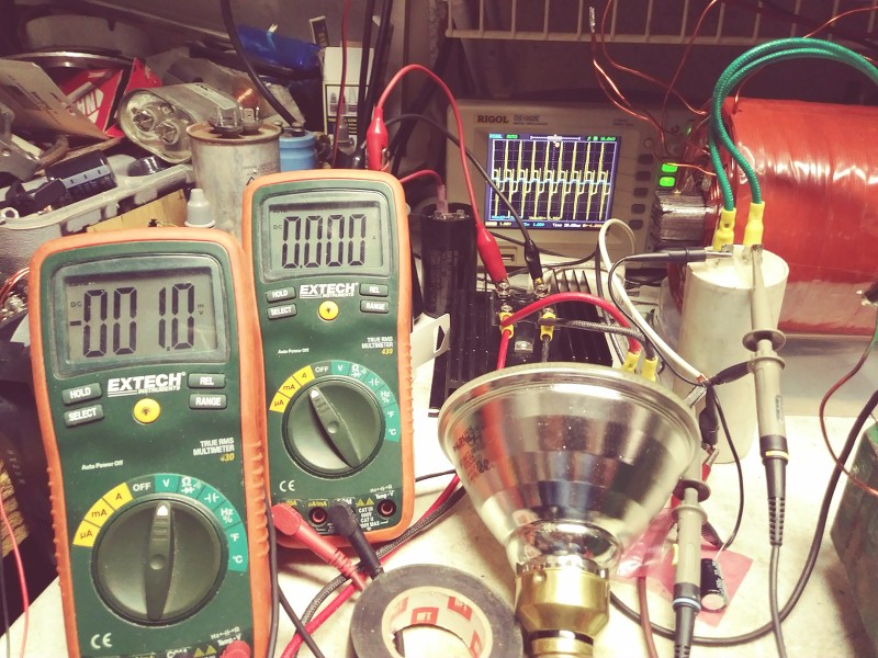
    HOWEVER, what about if I tell you that still is above zero volts when radically shorting out without Ammeter shorting it?...but just the two output wires from the secondary coil twisted together?


    So, no resistance from meter now (still connected but shorted terminals, so zero amps at its digital screen as seen above)...and still voltage does not drops to zero, V= Left Meter?

    You can see Scope Blue Chanel (Output) showing the small square wave...Yellow Chanel is Input.

    We only have left the resistance from the secondary coil being outputting the voltage under short?

    Please, be my guest, explain it now...


    Take care


    Ufopolitics
    Last edited by Ufopolitics; 01-27-2018, 06:34 PM.

    Leave a comment:


  • boguslaw
    replied
    Originally posted by bistander View Post
    Thanks for the interesting patent. It uses the 3-phase stator winding from a motor (or generator) to produce a rotating magnetic field. The rotor is replaced with a stationary iron member. There is no physical (mechanical) motion in the resultant machine. Yet it produces a rotating magnetic field when excited by a 3-phase source. I tried to explain this method to Ufopolitics when he started experimenting with moving fields in stationary cores.

    The patent claims that this rotating magnetic field can "generate" power in a winding which can be used to do work while also replacing the original excitation source. In other words, once started, it becomes a standalone electrical power source with no inputs, electrical, mechanical or otherwise.

    I wonder why this was never brought to market. It's like 16 years old. Just a few years left on the protection. And I imagine not too difficult to work around the weak (IMO) claims. Like isn't it essentially a wound rotor induction motor with a locked rotor? Or for that matter, like an alternator with a locked rotor?

    Regards,

    bi
    Looks like TPU ;-) Something like this was patented before in 40-ties if I remember correctly but only for one phase.

    Leave a comment:


  • seaad
    replied
    Thanks for your response bi.

    The main question here is: Does the "secondary" windings (locked squirrel cage windings) really perceive the non moving member and its rotating magnetic field(s) in the same way as a real magnetized rotating member with atoms and all flying by?
    The whole thing is just a wery complicated "transformer" anyhow!

    In the squirrel cage motor the squirrel cage is always lazy and goes slower than the rotating fields.
    Maybe this can be arranged by making the rotating exciter magnetic field go ahead the secondary with some degees (90 - 180) in the generator without moving parts. Or even faster =Hz depending of the load?

    Regards / Arne
    Last edited by seaad; 01-25-2018, 11:22 AM.

    Leave a comment:


  • bistander
    replied
    Thanks

    Originally posted by seaad View Post
    ...

    As you know I'm searching for the OU Effect so I'm reading now earlier posts in the Figuera thread. And this is a taste test which I think suits you and bistander except for the 3-phase angles.
    A stationary cylindrical electromagnetic core, made of one piece thin laminations stacked to desired height, having closed slots radially distributed, where two three-phase winding arrangements are placed together in the same slots, one to the center, one to the exterior, for the purpose of creating a rotational electromagnetic field by applying temporarily a three-phase current to one of said windings, and by this means, inducting a voltage on the second one, in such a way that the outgoing energy is a lot greater than the input. A return will feedback the system and the temporary source is then disconnected. The generator will run by itself indefinitely generating a great excess of energy permanently.


    Regards / Arne
    Thanks for the interesting patent. It uses the 3-phase stator winding from a motor (or generator) to produce a rotating magnetic field. The rotor is replaced with a stationary iron member. There is no physical (mechanical) motion in the resultant machine. Yet it produces a rotating magnetic field when excited by a 3-phase source. I tried to explain this method to Ufopolitics when he started experimenting with moving fields in stationary cores.

    The patent claims that this rotating magnetic field can "generate" power in a winding which can be used to do work while also replacing the original excitation source. In other words, once started, it becomes a standalone electrical power source with no inputs, electrical, mechanical or otherwise.

    I wonder why this was never brought to market. It's like 16 years old. Just a few years left on the protection. And I imagine not too difficult to work around the weak (IMO) claims. Like isn't it essentially a wound rotor induction motor with a locked rotor? Or for that matter, like an alternator with a locked rotor?

    Regards,

    bi

    Leave a comment:


  • seaad
    replied
    Originally posted by Ufopolitics View Post
    But I grasped something very interesting ..Are you referring to a potentiometer?

    but that costs a fortune

    What you may have missed...is that I do not get V drops to zero, not even when I short with amp meter
    About potentiometers. I'm using potentiometers very seldom. I'm using them to make rough measurements. Then I measure the pot value and change to a (some) fixed resistor(s) with nearest standard value, in parallel or in series if needed.

    At your low speeds it is possible to use bulbs but you have to calibrate them first and make a graph showing the relationship between voltage and current (at different Hz, mean values there). You have to be aware that bulbes are non linjer fellows which flickers at low speeds meaning that the Ohms fluctuates.
    At higher frequencies you have to include the coil (filament) existing inside the bulb ==> impedance (R & L).

    When you short cut the output with an amperage meter you are using the amperage meter built-in resistance (some Ohm / mOhms) across the poles. That's why you have some volts remaining there.

    As you know I'm searching for the OU Effect so I'm reading now earlier posts in the Figuera thread. And this is a taste test which I think suits you and bistander except for the 3-phase angles.
    A stationary cylindrical electromagnetic core, made of one piece thin laminations stacked to desired height, having closed slots radially distributed, where two three-phase winding arrangements are placed together in the same slots, one to the center, one to the exterior, for the purpose of creating a rotational electromagnetic field by applying temporarily a three-phase current to one of said windings, and by this means, inducting a voltage on the second one, in such a way that the outgoing energy is a lot greater than the input. A return will feedback the system and the temporary source is then disconnected. The generator will run by itself indefinitely generating a great excess of energy permanently.


    Regards / Arne
    Last edited by seaad; 01-24-2018, 08:11 AM.

    Leave a comment:


  • Ufopolitics
    replied
    Originally posted by seaad View Post
    -

    ...Open secondary with high Volts and the same made short cut with many Amps is not OU. I normally put a resistor across the output poles. Adjust it to give half the open Volts value.
    It is NOT just about reading higher voltages with no load...it is about Voltages Drops but NEVER reaching zero value (meaning, NEVER completely dead), NOPE!...to the point I can run AC Tools, like a fan or a drill, or a saw, etc,etc.

    But I grasped something very interesting you wrote above..."Adjust the Load Resistor"?...Now, I know you work with micro-voltages and milli-amps (no pun intended, honestly...)...Are you referring to a potentiometer?

    I find it interesting, since we would be able to regulate the load resistance, (like a variable load unit does, but that costs a fortune) then from there run the proper Ohms Law Calculations, measuring V Drop at terminals as amperage in series with variable resistor (potentiometer)...am I right?

    In my set up I would have to search for a specific higher wattage variable resistor (I have been searching for it previously for other uses, and they are also pretty hefty in price) which could run without burning up.


    Originally posted by seaad View Post
    Thats mostly near optimal output. Then I use that reading to compare with the input values to see if I got OU. . . .But I have certainly misunderstood you UFO?

    Regards / Arne
    Nope, You did not misunderstand me at all.

    What you may have missed...is that I do not get V drops to zero, not even when I short with amp meter...I have shown pics about it previously..remember?

    Regards


    Ufopolitics

    Leave a comment:


  • seaad
    replied
    -
    Listener192: "and just because a concept has a patent it does not mean that it works"
    If I remember right hanon told us, in some post, that a working unit (with OU??) was made and shown to the patent office. This was a must to get the patent issued. Correct me if I'm wrong.

    "the one you claimed O.U. on, I would have thought that you would be going all out to demonstrate test results that would support that finding"

    But s**t happens! The time will give us the answer.
    Open secondary with high Volts and the same made short cut with many Amps is not OU. I normally put a resistor across the output poles. Adjust it to give half the open Volts value. Thats mostly near optimal output. Then I use that reading to compare with the input values to see if I got OU. . . .But I have certainly misunderstood you UFO?

    "Most claims of O.U. turn out to be measurement errors."
    Thats right! In my case I used a formula suited for a normal transformer at my Bi-toroid-type transformer. Volt x Amp x Cos Thats probably wrong. But I have a bunch of guys beside me. Thane Heinz, Bill Alek, Bro . . .Normal transformers have Primary and Secondary on the same and only core.

    UFO: "When I am to prove OU, I go based on the Power Known Parameters, which are simply Voltage and Amperage from Input versus Voltage and Amperage at Output, which could easily obtain Wattage on both I/O levels, just by simply multiplying VXI=W."
    I agree to that. But it's not always possible.

    Regards / Arne
    Last edited by seaad; 01-23-2018, 06:27 PM.

    Leave a comment:


  • Ufopolitics
    replied
    Originally posted by Cornboy 555 View Post
    Hey UFO and all, i am still plugging away at this, but very time poor at the moment, with soooo much farm work.

    Am still working on 96 bar internal commutator, to supply G every second turn, still with a split Netica winding.

    My G is closely wound with 2mm wire, hoping to create enough induction in the toroid to limit the current flow.
    Will post on any progress as it happens.

    Best regards Cornboy

    Hello old friend!!

    Yes I know...life friend, that's the way it is.

    But I know you will finally get to it and so prove it works or not...


    Kind Regards


    Ufopolitics

    Leave a comment:

Working...
X