Announcement

Collapse
No announcement yet.

Re-Inventing The Wheel-Part1-Clemente_Figuera

Collapse
X
 
  • Filter
  • Time
  • Show
Clear All
new posts

  • Ufopolitics
    replied
    The Essence to Understand here...

    Originally posted by Listener192 View Post
    Hi UFO,

    I should point out, that if the input coil is only has a coupling coefficient <0.9 as would be the case with an open core, the coil current waveform would be as previously shown. If the coupling coefficient was say 0.999 i.e. a typical transformer, then the current waveform would be similar to the voltage waveform.

    L192
    Hello L192,

    Please, do not limit nor confuse yourself by comparing this device to a Transformer!

    The way to approach this device is to a typical Home Generator's Exciter Coil plus its OPEN, Rotating Core, and you will get your doubts cleared out and away.

    Once we are picturing the Exciter's Field of a Generator, spinning at 3600 RPM's...versus the TWO Points (the Two Output Coils) where Max Induction is reached...(whether are where majority of conductors are cut, or where BOTH cores "meet and align")** This is an old argument about where is that Generating Coils receive Max Induced EMF by the Exciter Field POSITIONING or ANGLE...and really, my point here is to ANALYZE FOR EITHER WAY, in order not to bring arguments AGAIN related to this "dilemma".


    Regards


    Ufopolitics
    Last edited by Ufopolitics; 08-25-2017, 04:36 PM.

    Leave a comment:


  • Listener192
    replied
    Current Waveform

    Hi UFO,

    I should point out, that if the input coil is only has a coupling coefficient <0.9 as would be the case with an open core, the coil current waveform would be as previously shown. If the coupling coefficient was say 0.999 i.e. a typical transformer, then the current waveform would be similar to the voltage waveform.

    L192

    Leave a comment:


  • Listener192
    replied
    With MOSFETS in H bridge

    Hi UFO,

    Attached is with MOSFETS and also showing power.

    L192
    Attached Files

    Leave a comment:


  • Listener192
    replied
    Simulator waveform

    Hi UFO,

    This is using an H bridge with ideal switches. MOSFETS give a similar but not quite square voltage waveform.

    Voltage in green, current in yellow.

    A 25uF cap makes little difference. It requires a very high value to make a sine wave.

    L192
    Attached Files

    Leave a comment:


  • Ufopolitics
    replied
    Originally posted by Listener192 View Post
    Hi UFO

    I ran a quick simulation on a 100mH coil fed by a +&- 30V supply with your wave form and although the voltage will rise and fall squarely the current will have a triangular waveform equal to the period. As flux follows current then induced output will also follow. With an added cap of say 25uF in parallel with the coil, then that triangle starts to turn into a sine. It will be interesting if you obtain something different.

    L192

    Leave a comment:


  • Listener192
    replied
    Coil current rise time

    Hi UFO

    I ran a quick simulation on a 100mH coil fed by a +&- 30V supply with your wave form and although the voltage will rise and fall squarely the current will have a triangular waveform equal to the period. As flux follows current then induced output will also follow. With an added cap of say 25uF in parallel with the coil, then that triangle starts to turn into a sine. It will be interesting if you obtain something different.

    L192

    Leave a comment:


  • Ufopolitics
    replied
    Probing Two Channels...

    Hello L 192,

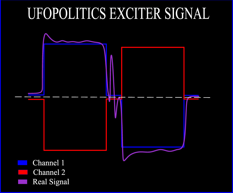
    This is what I believe the signal should look like, if we set one probe on each coil terminal...no ground used.

    The Purple one is just getting closer to the real way it should look, based on the ripples from coils plus spikes whenever entering Cap discharges...

    As you see both On Times takes place at same timing but reversed (alternated)


    Both signals are identical, except reversed...so on image there is a slight difference on second squares smaller than first, which is my error on graphic.

    Again, this is my "projection" based on the rotary switch that I have built...and I could be off.


    Regards


    Ufopolitics
    Last edited by Ufopolitics; 08-23-2017, 06:39 PM.

    Leave a comment:


  • Ufopolitics
    replied
    Originally posted by Listener192 View Post
    Hi UFO,

    so looking at this from the electronic switching aspect, can I leave the cap connected to the coil, or do I only need to connect the cap during the 45 degree period?

    L192
    Hello Listener192,

    That's a heck of a question friend!!

    The best answer I will give it to you from real testing...when I have the set up running...and while reading output...see if by connecting cap fixed to coil terminals, would do affect EMF Output or Not.

    It may work...as long as the cap capacitance would keep up with frequency speed, more likely a very small value, in order not to disturb the poles reversing timing (duration basically) to induce the right Output.

    Normally a Running Cap from a BRUSHLESS Home Generator would be rated pretty low capacitance...that could range from 25 to 40 mfd and generator would output same way with both values...(I already tested that)

    By all means, it could even "smooth" transitions...

    If it works it would be a great way to reduce Input from source to minimal levels whenever operational speed/hertz is reached.

    I am not too far to finish the rotary switch...just had some big time issues with one of my PC's BIOS...and stopped reading the main 1 terabyte HDD where I had most of CAD and works...thanks GOD, it was not a failed hard drive!!...I could read it and defragmented as clean it (CHKDSK) etc, on my other PC.


    Regards


    Ufopolitics

    Leave a comment:


  • Listener192
    replied
    Cap connection

    Hi UFO,

    so looking at this from the electronic switching aspect, can I leave the cap connected to the coil, or do I only need to connect the cap during the 45 degree period?

    L192

    Leave a comment:


  • Ufopolitics
    replied
    Being even more precise...

    Originally posted by Listener192 View Post
    Hi UFO

    So are you saying the coil floats during the 45 degree period, i.e. only connected to the capacitor?

    L192
    Hello L192,

    I want to be here MORE PRECISE...in my answer.

    My answer before was:

    Originally posted by Ufopolitics View Post
    Yes, that is quite the correct approach.
    I wrote "quite", because it is not precisely what I am doing on my switch...

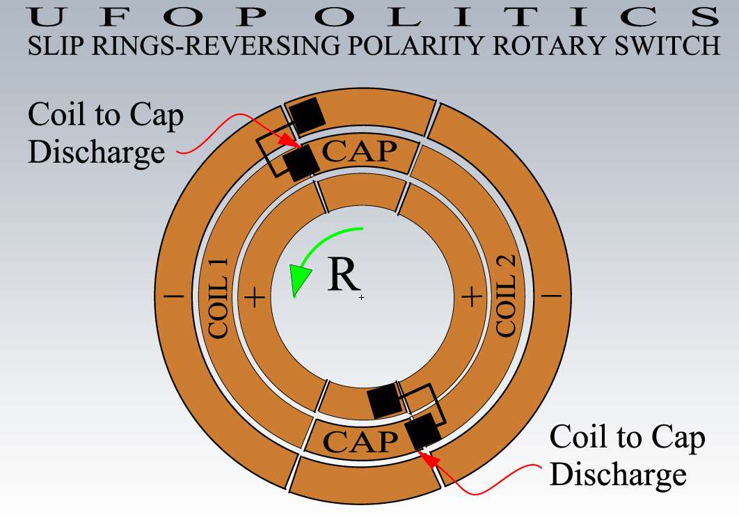
    Look at image below:


    First off, the R Green Arrow is wrong, it should be moving opposite (CLOCKWISE) in order to NOTE what I will explain below:
    Last edited by Ufopolitics; 08-23-2017, 01:40 PM.

    Leave a comment:


  • Ufopolitics
    replied
    Originally posted by Listener192 View Post
    Hi UFO

    This can be done with the same switching pulses, each switching two MOSFETS together one to + and one to - rails then all switches off for 45 degs then the alternate pair of MOSFETS are switched, these four MOSFETS being connected as an H bridge.

    L192
    Hi L192

    Great!!...if you say so...excellent!!


    See You tomorrow...


    Regards


    Ufopolitics

    Leave a comment:


  • Listener192
    replied
    Coil reversal

    Hi UFO

    This can be done with the same switching pulses, each switching two MOSFETS together one to + and one to - rails then all switches off for 45 degs then the alternate pair of MOSFETS are switched, these four MOSFETS being connected as an H bridge.

    L192

    Leave a comment:


  • Ufopolitics
    replied
    Originally posted by Listener192 View Post
    Hi UFO

    So are you saying the coil floats during the 45 degree period, i.e. only connected to the capacitor?

    L192
    Last edited by Ufopolitics; 08-22-2017, 07:20 PM.

    Leave a comment:


  • Ufopolitics
    replied
    Originally posted by Listener192 View Post
    Hi UFO

    Your waveform however, shows a positive excursion followed by a rest at zero followed by a negative excursion this implies that one end of the coil is ground or zero volts.

    Can you provide a new diagram that illustrates what you have said above?

    L192

    Hello L192,

    That wave I just "painted" it, based on just ONE Terminal signal...and it is just my "imaginary" interpretation from the rotary switch behavior...BUT, have NOT done it yet in reality.

    The actual signal from both coil terminals connected to probe and its ground...well, I have no idea what that one would look like...


    Regards


    Ufopolitics
    Last edited by Ufopolitics; 08-22-2017, 07:06 PM.

    Leave a comment:


  • Listener192
    replied
    Coil Reversal

    Hi UFO

    So are you saying the coil floats during the 45 degree period, i.e. only connected to the capacitor?

    L192

    Leave a comment:

Working...
X