Announcement

Collapse
No announcement yet.

Donald Smith Devices too good to be true

Collapse
X
 
  • Filter
  • Time
  • Show
Clear All
new posts

  • Originally posted by stupify12 View Post
    Tesla never mentioned of Resonance between Condenser and Inductor,

    Tesla only mentioned of the Harmonic Vibrations of the Inductor- Primary and Secondary.

    Read and Analyze what he describes on the patent.
    hehe well they didnt even have meters back then, but thats the same thing as Tesla saying
    "established rate of impressed oscillations to a coil and properly chosen condenser"
    ..i think he would've said.... meaning ~resonance~

    but its a mistake apparently that the L1 and L2 are 1/4 wave tuned there is not intended to be any such thing L1 to L2 as described by expert builders, ....those 2 coils are following basic transformer induction theory... but with a coupling close to 1 as possible in the case of the Magnifier.... the RESONATOR / extra coil... is the 1/4 wave tuned TRUE output of the intended system (if we are going for the BIG one anyway)
    In the beginner's mind, there are many possibilities.
    In the expert's mind there are few.
    -Shunryu Suzuki

    Comment


    • Originally posted by kEhYo77 View Post
      It seems that the key is to disturb the aether with a sharp HV impulse and use those local electromagnetic oscillations to charge a capacitor to high potential by the means of coil shorting, without damping the 'swing'. Important here is the coil of low self-inductance according to Tesla.
      A few turn, bifilar-in-series pancake coil, anyone?
      At 250,000 times the potential difference between turns of a single strand coil, in addition to the mutual cancellation of opposing mag fields, this seems to make sense. Tesla's own words here (Page 2, Line 5):
      Patent US512340 - NIKOLA TESLA - Google Patents

      Demonstrated in general sense here:
      Comparison of Tesla Bifilar and Pancake Coils - YouTube
      Bob

      Comment


      • @Bob Smith

        I've seen that video, it demonstrates this very well.
        One just has to look into Tesla's patents at the receiver end. The shorting is being done on the thick secondary coil of his transmission system. In simple terms Tesla's bifilar pancake coil topology is more efficient in capacitative coupling to the oscillations of electromagnetic environment, hence higher charge induced between the coil terminals in the video.
        “ THE PERSON WHO SAYS IT CANNOT BE DONE SHOULD NOT INTERRUPT THE PERSON DOING IT ! ”

        Comment


        • Originally posted by mr.clean View Post
          hehe well they didnt even have meters back then, but thats the same thing as Tesla saying
          "established rate of impressed oscillations to a coil and properly chosen condenser"
          ..i think he would've said.... meaning ~resonance~

          but its a mistake apparently that the L1 and L2 are 1/4 wave tuned there is not intended to be any such thing L1 to L2 as described by expert builders, ....those 2 coils are following basic transformer induction theory... but with a coupling close to 1 as possible in the case of the Magnifier.... the RESONATOR / extra coil... is the 1/4 wave tuned TRUE output of the intended system (if we are going for the BIG one anyway)
          From KehYo77
          One just has to look into Tesla's patents at the receiver end. The shorting is being done on the thick secondary coil of his transmission system. In simple terms Tesla's bifilar pancake coil topology is more efficient in capacitative coupling to the oscillations of electromagnetic environment, hence higher charge induced between the coil terminals in the video.
          Please forgive my simple query - just trying to put this together...
          - the secondary of the TMT would be a shorted series-wound bifi coil, as closely coupled to 1 with the primary as possible.
          - the resonant coil then would be 1/4 wave tuned to the shorted SBC?

          Thanks,
          Bob

          Comment


          • Originally posted by Bob Smith View Post
            - the secondary of the TMT would be a shorted series-wound bifi coil, as closely coupled to 1 with the primary as possible.
            - the resonant coil then would be 1/4 wave tuned to the shorted SBC?
            Exactly, simple, isn't it?
            “ THE PERSON WHO SAYS IT CANNOT BE DONE SHOULD NOT INTERRUPT THE PERSON DOING IT ! ”

            Comment


            • Originally posted by Bob Smith View Post
              At 250,000 times the potential difference between turns of a single strand coil, in addition to the mutual cancellation of opposing mag fields, this seems to make sense. Tesla's own words here (Page 2, Line 5):
              Patent US512340 - NIKOLA TESLA - Google Patents

              Demonstrated in general sense here:
              Comparison of Tesla Bifilar and Pancake Coils - YouTube
              Bob
              i don't mean to nit-pick, but this is verbatim from patent on :

              " the potential difference between adjacent turns now being 50 volts... energy Stored in the coil (capacitance) as a whole is now 250,000 as great"

              the idea is to neutralize the self-induction thru capacitance
              In the beginner's mind, there are many possibilities.
              In the expert's mind there are few.
              -Shunryu Suzuki

              Comment


              • Originally posted by mr.clean View Post
                i don't mean to nit-pick, but this is verbatim from patent on :

                " the potential difference between adjacent turns now being 50 volts... energy Stored in the coil (capacitance) as a whole is now 250,000 as great"

                the idea is to neutralize the self-induction thru capacitance
                Absolutely - Tesla's own words.
                I'm learning a lot from your posts, Kurt. Thanks for sharing so much.
                Bob

                Comment


                • Originally posted by Bob Smith View Post
                  Please forgive my simple query - just trying to put this together...
                  - the secondary of the TMT would be a shorted series-wound bifi coil, as closely coupled to 1 with the primary as possible.
                  - the resonant coil then would be 1/4 wave tuned to the shorted SBC?

                  Thanks,
                  Bob
                  im not sure i follow, maybe you could wind it bifilar, but for the TMT it is basically primary right around secondary base (or if insulated well enough, surrounding secondary as the patent shows)

                  to solve the issue of L1 and L2 tuning, they should have equal surface area is the big thing, and will consequently weigh very closely depending on thickness of both inductors.

                  the extra coil/Resonator is the same gauge or slightly less than secondary, and should be 3 to 4 times the inductance of the secondary, then connected from top of sec, to base of XCoil... slightly concatenated but far enough away from L1, yet still inside L2 , seems best at the moment

                  also read that the topload capacitance should dwarf the resonator (Tesla had a huge Topload toroid)
                  there's info out there, search for Magnifier Transmitter and namely Richard Hull and Eric Dollard

                  and yes, the Resonator is tuned to a quarter of its natural wavelength directly to its base, as well as being induced, as well as having a non-zero v starting voltage (base of coil is secondary hot end) so it ends up using the topload capacitance as the ground reference, pretty much backwards situation from normal
                  Last edited by mr.clean; 06-01-2013, 07:04 AM.
                  In the beginner's mind, there are many possibilities.
                  In the expert's mind there are few.
                  -Shunryu Suzuki

                  Comment


                  • Originally posted by mr.clean View Post
                    also read that the topload capacitance should dwarf the resonator (Tesla had a huge Topload toroid)
                    there's info out there, search for Magnifier Transmitter and namely Richard Hull and Eric Dollard

                    and yes, the Resonator is tuned to a quarter of its natural wavelength directly to its base, as well as being induced, as well as having a non-zero v starting voltage (base of coil is secondary hot end) so it ends up using the topload capacitance as the ground reference, pretty much backwards situation from normal
                    Polarization of aether's virtual particle domains with magnetic force is equally important to electric potential polarization and capacitative coupling. Geometry plays here significant role.

                    We want to attract/polarize surrounding environement by creating a HV dipole.

                    The more surface contact area there is (insulated!) the better.
                    We do not want to make a lightening/discharge from the surrounding!
                    It's a power loss when charge escapes from our dipole


                    We only need to polarize electrically surrounding environement! Think of trees now... The shape of a tree is nature's best fractal geometry for equal charge/mass ratio distribution in 3D space!
                    The other dipole lies beneath the surface of the earth.
                    In my opinion trees' branching fractal is the best candidate for polarizing space due to surface area They draw the energy this way!
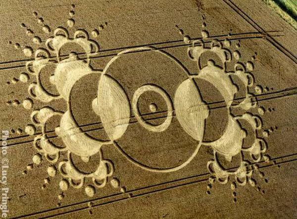
                    Even this crop circle depicts this topology

                    Avisio is using an antenna as well, even he is calling it this way.
                    Last edited by kEhYo77; 06-01-2013, 01:35 PM.
                    “ THE PERSON WHO SAYS IT CANNOT BE DONE SHOULD NOT INTERRUPT THE PERSON DOING IT ! ”

                    Comment


                    • Originally posted by mr.clean View Post
                      im not sure i follow, maybe you could wind it bifilar, but for the TMT it is basically primary right around secondary base (or if insulated well enough, surrounding secondary as the patent shows)

                      to solve the issue of L1 and L2 tuning, they should have equal surface area is the big thing, and will consequently weigh very closely depending on thickness of both inductors.

                      the extra coil/Resonator is the same gauge or slightly less than secondary, and should be 3 to 4 times the inductance of the secondary, then connected from top of sec, to base of XCoil... slightly concatenated but far enough away from L1, yet still inside L2 , seems best at the moment

                      also read that the topload capacitance should dwarf the resonator (Tesla had a huge Topload toroid)
                      there's info out there, search for Magnifier Transmitter and namely Richard Hull and Eric Dollard

                      and yes, the Resonator is tuned to a quarter of its natural wavelength directly to its base, as well as being induced, as well as having a non-zero v starting voltage (base of coil is secondary hot end) so it ends up using the topload capacitance as the ground reference, pretty much backwards situation from normal
                      Very helpful, and I'm sure the product of a lot of reading, trial and error. I appreciate the sharing.
                      Bob

                      Comment


                      • Shill hunting !

                        I will demonstrate the evil Shill ´Farmhand´ See my comments in between.

                        Originally posted by Farmhand View Post
                        Hi John, I agree 100%.

                        -IF YOU STAYED OUT THERE WOULD BE 3500 POSTINGS LESS CRAP !

                        My advice would be to use the original schematic from
                        Don's own PDF's.

                        -DON SMITH HAS NEVER GIVEN GIVEN ANY GOOD SCHEMATIC !

                        One example for the table top device I think you refer to, is the positioning of
                        the spark gap and capacitor in the primary circuit. Some of the pictures
                        supposedly of Don's device don't fit with the drawings and show connections
                        which do not work well in any way of looking at it in my experience.

                        -IS NO HELP AT ALL.

                        Things are up in the air so to speak because Don contradicts himself so much
                        and seems to say things that make no sense and for which there is no proof.
                        ie. the resistor divider correcting the voltage and a resistor changing the frequency thing.

                        -A GOOD LIAR DOESN´T ALWAYS LIE, LIKE HERE.

                        If you ignore all the Patrick Kelly book variations and all the posted opinions
                        and look at what Don says and shows, that would be a good starting point,
                        that way you can skip all the accumulated muck and make your own assessments.

                        -THE OPPOSITE ! PATRICK KELLY HELPS TO CLEAR THINGS ! DON DOESN´T.

                        The attached drawing shows the spark gap so that it will work ok but the
                        pictures I have seen of the actual device show a connection that is different
                        and won't work well or at all.

                        -THE TRICK IS NOT IN THE SPARK GAPS !

                        There is no point to anyone making a step by step build instructional, because
                        no one has a device that does what Don claimed.

                        -SO WHY IS HE HERE SO MASSIVELY IF HE DOESN´T BELIEVE IN IT !??

                        Personally I'm inclined to say he pulled a good fake and it may have been for a multitude of reasons, maybe even just for his own fun.

                        -NO, HIS FEAR. HE GIVES A FAR BETTER SCHEMATIC IN HIS DVD !

                        Cheers

                        KEEP YOUR CHEERS

                        -AND HE IS NOT THE ONLY SHILL HERE, MESSING THINGS UP HERE !!!

                        Its time for a knowledgeable and honest moderator here also.

                        Comment


                        • Originally posted by Bob Smith View Post
                          Very helpful, and I'm sure the product of a lot of reading, trial and error. I appreciate the sharing.
                          Bob
                          no problem Bob, hehe yes a lot of reading, and Tesla's patents are not the simplest to understand

                          Excellent work in going thru original patents yourself tho, it's really the best place to look
                          In the beginner's mind, there are many possibilities.
                          In the expert's mind there are few.
                          -Shunryu Suzuki

                          Comment


                          • Clemente Figuera Generator

                            A.k.a Electro Dynamic Induction Machine.

                            What your looking for is the very simple idea of the TMT is base solely on the Asymetric Toroid Transformer of Tesla, Read all the patents of tesla, the patents which is related to transformers that he improved very much to feed it with hv natural impulse high frequency oscillation of the condenser and analyze it very well.

                            The so called Lenzless Generator or In phase Generator- not really in phase, but compensated by the Double Helix wave form which he created on the Primary coil. Any load or how Many Receiving Coil we put on the Secondary coil, the primary never degrade or detect its power as Don smith told as.

                            The picture below try to re draw it a form of Pancake coil. The Spark gap was the switch for HV, Air core because of the Heating problem, Pancake Transmitter because Only 1 set of coils/2 pair of coils was use on that transmitter, another set of coils for Receiver, Analyze how the same he would that transformer to Tesla TMT.

                            Just an oponion from a beginner. Just ignore it.
                            Attached Files
                            Last edited by stupify12; 06-01-2013, 06:41 PM.

                            Comment


                            • Farmhand

                              Originally posted by Hobby Eon View Post
                              I will demonstrate the evil Shill ´Farmhand´ See my comments in between.


                              -AND HE IS NOT THE ONLY SHILL HERE, MESSING THINGS UP HERE !!!

                              Its time for a knowledgeable and honest moderator here also.
                              Hi there HobbyEon, I know you are defending the greater good, but you have the wrong impression of Farmhand

                              Farmhand is actively building and his work really speaks for itself, very good and he has a lot of experience

                              I snapped once as well at one thing or another he told me but he is just a no bull$hit kind of dude.

                              The thing is to balance realism and optimism... he is a realist... and may come across as a hard ass, but he keeps building (showing optimism)

                              You can see his work on youtube AlternateFarmhand1 I believe it is

                              he never sounds very thrilled on video, but he has some Great work on various Tesla stuff... and he knows about the Magnifier, so he cant be all bad hehe
                              In the beginner's mind, there are many possibilities.
                              In the expert's mind there are few.
                              -Shunryu Suzuki

                              Comment


                              • Originally posted by quantumfuel View Post
                                You're exactly relevant and right T-1000.
                                I don't know from where you've got this deduction, but I came to the same conclusion after years of reflexions and studies.

                                More exactly, the quantum medium is known to polarize by creating pairs of electron-positron. There is also presumptions that gammas are created at a lesser level of energy. This is exactly what occurs in cosmic rays, which is already a natural free-energy production that comes from the random conditions in the ambient aether.

                                To sum-up the system :
                                - high frequency high-voltage disrupts provoke scalar waves which constitute the physical borders of photons
                                - scalar waves provide the wave guides in which high energy photons emerge from out the ambient space energy
                                - according to the level of energy involved, these photons can be split a t their turns into an electron-positron pair.

                                The success of the free-energy capture operation relies therefore in the ability of the electric circuit to convert all these space creations into usable electricity.

                                Clear and obvious!
                                Yeah just great info T-1000,

                                Oh and hey Quantum, your analogy may be correct, but from hearing Eric Dollard on various waves...
                                According toJJ Thompson, Maxwell, Heaviside, Tesla, Steinmetz and Alexanderson (hehe i watch too much Dollard) ...
                                There are only 2 kinds of waves... Hertzian-Transverse, and LMD(Longitudinal Tesla style, but was regognized to exist before Tesla used it)

                                However, there ARE such things as ~Standing~ waves.... And Scalar ~Transmission~

                                If u replace those terms in your analogy where u mentioned "scalar waves", i know Eric Dollard for one, would like it

                                Also, there must be a guide for a wave to travel thru, not sure if a wave could be the guide
                                Last edited by mr.clean; 06-02-2013, 05:59 PM.
                                In the beginner's mind, there are many possibilities.
                                In the expert's mind there are few.
                                -Shunryu Suzuki

                                Comment

                                Working...
                                X