Announcement

Collapse
No announcement yet.

Donald Smith Devices too good to be true

Collapse
X
 
  • Filter
  • Time
  • Show
Clear All
new posts

  • Originally posted by African View Post
    Hi All
    I have followed this thread for a wile now and have collected parts to build my first unit, after trying many different Nst,s I had to settled on a line transformer from an old B&W TV and I am using a 555timer to run it at about 27Khz at 58% duty cycle with a old computer power supply that gives me a output of 40W but my results were poor so I decided to try to run it on a duty cycle of 85% and then I started to get great sparks out of that up to about 30mm long. I took a 4ft 20W FL tube and by just holding it against the transformer it lights up but my calculations was not accurate
    After when I checked again I realized that I am running at only 2.132 KHz but my results were good. My question is this should I continue with this frequency or go with the recommended frequencies of 27 kHz to over 30 kHz.
    Mr. Clean you are a good person and I have followed your progress and enjoyed your vids can you give me some advice on how to go from here. And thank you for sharing so generously
    Best Regards
    Johan
    Hello African, best regards sir!

    I have a question for you as I am presently working on a driver circuit to power my hand wound air gap coils as a hand made lower voltage DIY NST setup. and I was simply changeing a 12v DC to 120v AC inverter schematic to a variable frequency 50% duty cycle arrangement. (the schematic is attached in the thumbnail if anyone is interested.) My question is how did you change the duty cycle of the 555 in your circuit to 85% as that interests me greatly. your information will be appreciated truly sir! thanks in advance, mike,onward!

    BTW - I am changeing the R4 pot to an 1M 3watt potentiometer to vary my frequency to achieve reasonance of my hand wound air gap coils. Also the T1 transformer will be replaced by my hand wound coils. all of this should give me a nice lower voltage NST power supply to drive an L1 smith type coil. I am like you in having tried different type NST,s in the past. but hopefuly with this setup I will have cured that LOL!!! also the transistors I am useing are the old standbys a 2N3055 NPN and a MJ2955 PNP.
    Last edited by clarence; 01-08-2013, 04:30 PM.

    Comment


    • 555timer

      Hi Clarence
      My best regards to you to Sir
      I use a little program called Electronics Assistant it is handy tool
      If you Google it you should find it easy if not I can send it to you
      My setup is about the same as yours but I am using a single transistor Bd243c
      My 555timer is setup like this R1=4.7K R2=1K C1=100nf duty cycle at 85%
      It gives me this 2.132 KHz.
      I hope this helps
      Best to you
      Johan

      Comment


      • 555 timer

        Just in passing
        I have tried to run my setup on 27khz but the current were low when I tried to change it to a duty cycle of 85% I used the wrong cap hence the 2.132 KHz. But it was a good mistake the current became a lot stronger I stuck my finger into that long spark and I can say for sure that I am truly enlightened now lol

        Comment


        • Originally posted by African View Post
          Just in passing
          I have tried to run my setup on 27khz but the current were low when I tried to change it to a duty cycle of 85% I used the wrong cap hence the 2.132 KHz. But it was a good mistake the current became a lot stronger I stuck my finger into that long spark and I can say for sure that I am truly enlightened now lol
          Hello African , thanks for the light!

          I do appreciate your info back sir! I wiil definetly use the program you mentioned. thank you again and LOL!!
          mike,onward!

          Comment


          • Originally posted by mr.clean View Post
            Big caps? you mean the 2600 Farad in 12.5v series? or the 2000v 40uf? hehe

            yes they run awesome, but right now my PVM500 is down
            And when i do new videos i want them to be improvements on the previous, so until i get that dealt with i am kinda hooped
            But it motivated me to try the 60 hz LC which was a success, so that was nice

            yeah thats crappy about the circuit stopping on you, oh and an instant way to tell if you are really putting in more than you are using is to parallel caps up to your battery, then remove the battery and keep the caps in place i havent tried it yet with my smith board, but the radiant circuit i was playing with a while back in fact went 3 or 4 days on the battery from 12.04v or so to 12.31v with the cfl's going, i actually turned it off cause the battery was charged LOL
            i then tried using a different setup and eventually lost interest, hehe. but i should actuall re-build it and try running on the caps

            in trying to move ahead, on my driver i replaced the fuse and 555, and still nothing
            so im thinking of bypassing the AC input in the driver, and tapping into the circuit at the 12v component, cause on the schem there is a built in stepdown trafo to be driven by AC source.
            So bypass and use DC i think, then trouble shoot from there.

            hehe but is there something in particular u want to see about the caps?

            Hey actually one more thing, last time i was charging and running on the big 2600F, the diodes i put in full wave failed and went up in Violent Smoke!!
            Anyone know what did that? Too much current thru? or trying to hold too much reverse current?
            Do you have the schematic of this radiant circuit that you mentioned?
            Yes for 2600F I think it's alot for those poor diodes Maybe you should try to get bigger once.
            Originally posted by Farmhand View Post
            Hi Guruji, Maybe what you are seeing is the normal action of the battery.
            With a lead acid battery (not sure about others) when the battery is fully
            charged then a reasonable load is connected what happens is the battery
            voltage initially drops because of the load, but after a short time when the
            chemical action of the battery catches up with the demand of the load and
            exceeds it the dropping voltage reverses and the battery voltage rises for a time,
            but it never exceeds the fully charged voltage.

            I can demonstrate this. Battery begins at about 12.8 volts then a 1.5 amp or
            so load is added to the battery, the voltage drops from 12.8 to around 12.20 volts
            in a few minutes then it starts to rise again. Depending on the load it may rise
            back up to 12 .40 volts over a period of a few minutes maybe 10 minutes, not
            so easy to show on video but I can and will do it. Anybody should be able to
            do this and see it themselves.

            This is normal battery behavior. It shows the battery doing it's chemical thing
            to try to maintain the voltage at it's terminals when a load is added.

            I'm not saying for sure this is what you see Guruji, just offering up a possible
            reason for seeing a rising voltage of a battery that is loaded.

            Cheers
            Hi Farmhand yes maybe it's what you've saying what I was seeing ; but sometimes our wants would go beyond realities
            Ok thanks guys for response.

            Comment


            • Originally posted by African View Post
              Hi All
              I have followed this thread for a wile now and have collected parts to build my first unit, after trying many different Nst,s I had to settled on a line transformer from an old B&W TV and I am using a 555timer to run it at about 27Khz at 58% duty cycle with a old computer power supply that gives me a output of 40W but my results were poor so I decided to try to run it on a duty cycle of 85% and then I started to get great sparks out of that up to about 30mm long. I took a 4ft 20W FL tube and by just holding it against the transformer it lights up but my calculations was not accurate
              After when I checked again I realized that I am running at only 2.132 KHz but my results were good. My question is this should I continue with this frequency or go with the recommended frequencies of 27 kHz to over 30 kHz.
              Mr. Clean you are a good person and I have followed your progress and enjoyed your vids can you give me some advice on how to go from here. And thank you for sharing so generously
              Best Regards
              Johan
              hi buddy, im curious what kind of coils you are using for your driver?
              I tried using ignition coils, and i expected 30-100khz, but the ignition coils core would saturate at 3-5khz.
              So i moved to a driver that uses a C-core ferrite, rated for 100Mhz before saturation.
              i really noticed better usable frequencies in the proper range.
              It can "work" with most any NST, because of the spark hitting many frequencies as T1000 has said, but significantly improved with the tuned frequency.
              In the beginner's mind, there are many possibilities.
              In the expert's mind there are few.
              -Shunryu Suzuki

              Comment


              • new vid

                Hi everyone, turning up the input power a little here, and it killed a string of bulbs, so wanted to show you all before they all burned out
                then show how it's outputting some serious current, was welding the wires together and had to pull them apart at times.

                Input was about 72 watts, i did have all 5 lights going earlier...100 watts worth. but then i took off 2 and the 3 burned out LOL, so i showed 2 in the vid for a few seconds before they burned out.
                This was due to the voltage being so high, and there was enough current supplied as well (otherwise the lights just arc over, not get cooked )

                output voltage was enough to blast thru and light up all bulbs, and output current was enough to completely burn them out.

                not new but its interesting how from open circuit to full load there is no extra current demand from the source, showing real power on L2, and indicating all reactive power on L1. no actuall primary current used by secondary. sounds funny, but how else to explain how no extra current demand under load?
                And with the resonant NST circuit, there is 1,2 amps doing 2,6 amps of work

                Once my high freq driver is back up, i expect even better results than this!
                And i find that its best to use as much capacitance on primary as your spark gap can handle before your gap starts to fire under 60hz and you notice it flashing

                Don Smith Device Project Part 36: Experimenting with Higher Capacitance and Welding Wires - YouTube
                Last edited by mr.clean; 10-05-2012, 07:48 AM.
                In the beginner's mind, there are many possibilities.
                In the expert's mind there are few.
                -Shunryu Suzuki

                Comment


                • Originally posted by mr.clean View Post
                  Hi everyone, turning up the input power a little here, and it killed a string of bulbs, so wanted to show you all before they all burned out
                  then show how it's outputting some serious current, was welding the wires together and had to pull them apart at times.
                  Input was about 72 watts, output voltage was enough to blast thru and light up all bulbs, and output current was enough to completely burn them out.

                  not new but its interesting how from open circuit to full load there is no extra current demand from the source, indicating all reactive power and no primary current used by secondary?

                  Don Smith Device Project Part 36: Experimenting with Higher Capacitance and Welding Wires - YouTube
                  What is the 72 Watts doing if it is not powering the secondary ? Most of the
                  power put into the primary is going to the secondary, and if the output
                  voltage is not smoothed the voltage spikes could cause spiking of the current
                  through the load, so the bulbs could have been killed by higher voltage or
                  higher current "spikes".

                  So even a constant input of 5 Watts could cause a spiking output or a built
                  up output enough to blow the bulbs.

                  Looks interesting though and I like the sound.

                  In my opinion you need to rectify and smooth the output then pulse it though
                  the load or make continuous AC with an even amplitude to it. Either way for a
                  measurement of the output power the easiest way is to measure smoothed
                  DC, and for the input a killo watt meter should work if it's wall power and far
                  enough away from the setup. The kilowatt meter will show you your
                  "corrected" power factor as well as input power.

                  If that's an AC meter which it looks like it is then it is measuring current both
                  ways, you don't pay for what goes back only what doesn't go back. The
                  effect of the power factor correcting capacitors is to keep "local" the reactive
                  power so less is sent back to the supply, it is good for sure but the efficiency
                  is still much the same.

                  A power factor of 0.8 means that 20 % of the input power is returned to the
                  supply, this is not paid for. A power factor of 0.2 means that 80 % of the
                  input is returned to the supply this is not paid for either. A power factor of
                  1.0 means none of the input is returned to the supply so it's all paid for.
                  Only the power that is consumed is paid for.

                  Reactive power is input power being returned to the supply, when the
                  reactive power is corrected by a capacitor it stays local, it is then used a real
                  power, therefore the only current that flows in a system with a power factor
                  of 1.0 is the amount of current consumed.

                  Cheers
                  Last edited by Farmhand; 10-05-2012, 07:47 AM.

                  Comment


                  • Actually you need those spikes to run much more power hungry Rotoverter and it would not be possible to do same with DC/AC from smoothed spikes.
                    Last edited by T-1000; 10-05-2012, 08:00 AM.

                    Comment


                    • Originally posted by Farmhand View Post
                      What is the 72 Watts doing if it is not powering the secondary ? Most of the
                      power put into the primary is going to the secondary, and if the output
                      voltage is not smoothed the voltage spikes could cause spiking of the current
                      through the load, so the bulbs could have been killed by higher voltage or
                      higher current "spikes".

                      So even a constant input of 5 Watts could cause a spiking output or a built
                      up output enough to blow the bulbs.

                      Looks interesting though and I like the sound.

                      In my opinion you need to rectify and smooth the output then pulse it though
                      the load or make continuous AC with an even amplitude to it. Either way for a
                      measurement of the output power the easiest way is to measure smoothed
                      DC, and for the input a killo watt meter should work if it's wall power and far
                      enough away from the setup. The kilowatt meter will show you your
                      "corrected" power factor as well as input power.

                      If that's an AC meter which it looks like it is then it is measuring current both
                      ways, you don't pay for what goes back only what doesn't go back. The
                      effect of the power factor correcting capacitors is to keep "local" the reactive
                      power so less is sent back to the supply, it is good for sure but the efficiency
                      is still much the same.

                      A power factor of 0.8 means that 20 % of the input power is returned to the
                      supply, this is not paid for. A power factor of 0.2 means that 80 % of the
                      input is returned to the supply this is not paid for either. A power factor of
                      1.0 means none of the input is returned to the supply so it's all paid for.
                      Only the power that is consumed is paid for.

                      Reactive power is input power being returned to the supply, when the
                      reactive power is corrected by a capacitor it stays local, it is then used a real
                      power, therefore the only current that flows in a system with a power factor
                      of 1.0 is the amount of current consumed.

                      Cheers
                      well i say that loosely, because yes obviously the secondary is powered by primary, but whether open or shorted or fully loaded, the input current is always constant.

                      hehe and from your work you must know what i mean..

                      Dont the laws state that an induced voltage on secondary will cause a lowering of impedance in primary and cause it to draw more current to maintain the voltage across secondary?
                      Here the current in primary is always "idling".

                      But you're right, it "is" powered by primary, but not showing any extra current demand.... which it should be, under load right?
                      In the beginner's mind, there are many possibilities.
                      In the expert's mind there are few.
                      -Shunryu Suzuki

                      Comment


                      • last post with edits

                        Hi everyone, turning up the input power a little here, and it killed a string of bulbs, so wanted to show you all before they all burned out
                        then show how it's outputting some serious current, was welding the wires together and had to pull them apart at times.

                        Input was about 72 watts, i did have all 5 lights going earlier...100 watts worth. but then i took off 2 and the 3 burned out LOL, so i showed 2 in the vid for a few seconds before they burned out.
                        This was due to the voltage being so high, and there was enough current supplied as well (otherwise the lights just arc over, not get cooked )

                        output voltage was enough to blast thru and light up all bulbs, and output current was enough to completely burn them out.

                        not new but its interesting how from open circuit to full load there is no extra current demand from the source, showing real power on L2, and indicating all reactive power on L1. no actuall primary current used by secondary. sounds funny, but how else to explain how no extra current demand under load?
                        And with the resonant NST circuit, there is 1,2 amps doing 2,6 amps of work

                        Once my high freq driver is back up, i expect even better results than this!
                        And i find that its best to use as much capacitance on primary as your spark gap can handle before your gap starts to fire under 60hz and you notice it flashing

                        Don Smith Device Project Part 36: Experimenting with Higher Capacitance and Welding Wires - YouTube
                        In the beginner's mind, there are many possibilities.
                        In the expert's mind there are few.
                        -Shunryu Suzuki

                        Comment


                        • Originally posted by Gedfire View Post
                          Hi Soundiceuk,

                          Are ALL of Don's Videos available on DVD?

                          1996 to 2005?

                          High quality, unedited.Or can I get unedited versions like the Zero Point Energy Interview?

                          Ged
                          Hi Ged, there is talk of a USB flashdrive with all the original videos and Don's notes, pdf's being made available.

                          My thoughts about your spark gap question are that there needs to be something making and breaking the circuit, Tesla wasn't using transistors and he was using an oscillator.

                          I haven't seen any old oscillators that don't have some sort of spark.

                          If it didn't oscillate then there would be no pumping effect.

                          What is a spark? gas, solid, liquid, plasma or something else?

                          Comment


                          • NICE WORK<EXPLANATION<DETAILS<-thanks

                            Originally posted by mr.clean View Post
                            well i say that loosely, because yes obviously the secondary is powered by primary, but whether open or shorted or fully loaded, the input current is always constant.

                            hehe and from your work you must know what i mean..

                            Dont the laws state that an induced voltage on secondary will cause a lowering of impedance in primary and cause it to draw more current to maintain the voltage across secondary?
                            Here the current in primary is always "idling".

                            But you're right, it "is" powered by primary, but not showing any extra current demand.... which it should be, under load right?
                            Hello Mr. Clean,

                            really enjoyed your vid and did pocket my own observations per Don Smith criteria (you know what I mean Clean-hehe, small miniature pun not meant to be harmful). am waiting for last of components for my driver build. seems like things take forever- oh well.
                            When my driver is built it will have air gap reasonant DIY coils (to eliminate the cemf or bemf buzz) and will be a low voltage output to L1 (approx 400 v).
                            the secondary output will be approx 2400v reasonant with L1 and driver. the power source for ALL of my circuit will be my 7ah gel cell to eliminate any association with mains. and as soon as I have the established output from L2 secondary I will add two or more L2,s Don smith style and then observe the driver output impedance when ALL of the L2,s are uder a load. I already know what the results will be but Ill just keep that to myself for now, Im sure you understand.
                            Just really wanted to say good work and that I havent gone away - just idling till parts come in. mike, onward!

                            Comment


                            • This and that

                              Hi Mr. Clean
                              I am using a line transformer from and old B&W TV I do not know what the primary and secondary windings are I first try to run it at 27khz 58% duty cycle as I said but I think that I got the sweet spot by mistake when I calculated the cap 100 nf to run at 85% duty cycle but when I looked at it again the frequency was only 2.132khz as I am only a beginner in this I do not know if this is good or if I should go for a higher frequency but the current output looks promising

                              @Clarence
                              Hi
                              Let us know if by changing the duty cycle on your system has worked
                              Thank you all
                              Best regards,
                              Johan

                              Comment


                              • Hi mr clean

                                Dont the laws state that an induced voltage on secondary will cause a lowering of impedance in primary and cause it to draw more current to maintain the voltage across secondary?
                                I don't know about laws saying that, I think it depends on the difference in
                                phase or not, it depends what you want, it's a free world.

                                But you're right, it "is" powered by primary, but not showing any extra current demand.... which it should be, under load right?
                                Not really, again it depends, you can hardly call an unchanging 70 watts or so
                                "idling". If it doesn't change then that's the power, full. The advantage of an
                                idling transformer is that our friend Back emf reduces the input current when
                                there is no load to very little to conserve energy when there is no load, but it
                                can still provide power on demand and also receive back power, maybe.

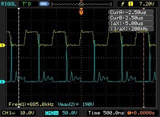
                                Here's a video of a light bulb powered by 12 volts and producing voltage
                                spikes over 180 volts, they would be higher but they are clamped by a GDT.
                                The voltage is the result of the energy stored in the magnetic field of the
                                coiled filament, it's 10 uH, with 3 nF it should be resonant at about 920 Khz.

                                Light bulb spikes - YouTube


                                I wonder if I can do a resonant power transmission using two light bulbs.
                                Other things also come to mind to try.

                                Cheers

                                Comment

                                Working...
                                X